Week -2
OBJECTIVE 1: Make a Simulink model of Doorbell using solenoid block with the following conditions-
- When the switch is closed the electromagnet receives electrical power from the battery and pulls the metal arm to hit the bell producing sound.
- If the switch is closed for 2 seconds and then released, then Observe the physical movement of the plunger.
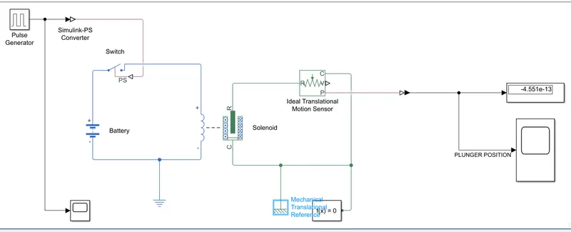
So to create a simulink model of Door Bell, first we will take a 'Solenoid' block and then a 'Battery' block & a 'Switch' block to connect with 'Solenoid' block. Negative terminal of 'Solenoid' will be connected to negative terminal of 'Battery'. 'Switch' will be connected in-between positive terminal of 'Solenoid' and positive terminal of 'Battery'. Make sure a 'Electrical Referance' is connected with negative terminal of 'Battery' and 'Solenoid'. To control the 'Switch' a 'Pulse Generator' block will be connected to PS terminal of 'Switch' block. As 'Pulse Generator' is a Simulink block, so a 'Simulink-PS Converter' block have to connect in between them.
An 'Ideal Translational Motion Sensor' block have to connect to mechanical part of 'Solenoid', to measure the translational motion of plunger. R port of 'Solenoid' and 'Ideal Translational Motion Sensor' will be connected. Make sure C port of both block will be connected to a Mechanical Translational Reference' block. Also a 'solver' must be connected to that C port. To observe the translational motion of plunger P port 'Ideal Translational Motion Sensor' block will be connected to a 'Scope' and a 'Display'.
So the final model will look like-
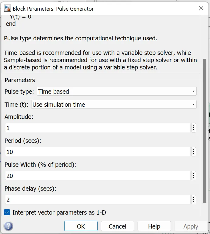
To run this model, first parameter of 'Pulse Generator' have to set in proper value. Make sure Phase Delay will be 2 sec. and Pilse Width will be 20%.
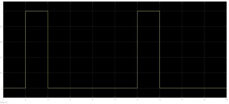
So the output pulse will be-
Now after running the model we can see the movement of the plunger-
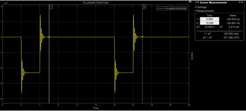
So from this plot we can see that for first 2 sec. switch is off when no movement is noticed for plunger. For next 2 sec.(2 to 4 sec.) plunger hits the bell and vibrate and slowely stable.
Simulink file:- https://drive.google.com/file/d/1CZ3nsiK0NR2CIWkVjzL38zu-6PiA9gN7/view?usp=sharing
OBJECTIVE 2: Make a simulink model where a thermistor will be used to sense the temperature of a heater & turn on or turn off the fan as per the below conditions-
- Temperature source: 20 °C from 0 to 10 seconds, 27 °C from 10 to 30 seconds, 23 °C from 30 to 50 seconds
- Fan conditions: ON if the temperature above 25 °C, OFF otherwise
Magor blocks used in this model are-
- Thermistor
- Voltage Sensor
- Controlled Temperature Source
- Switch
- Signal Builder
And some other blocks are also used here, like- 'Battery', 'Resistor', 'Solver Configuration', 'Thermal Reference', 'Electrical Reference', 'Scope', 'Display', 'Constant', 'PS-Simulink
Converter' & 'Simulink-PS Converter'.
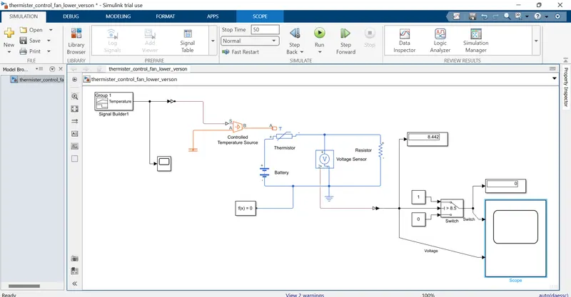
First take a 'Thermistor' block and place it. Then take a 'Controlled Temperature Source' block to give input to 'Thermistor' through T port. In 'Controlled Temperature Source' block what ever input will take from port S that will be send to port B. And make sure port A is connected to a 'Electrical Reference'. Now a 'Signal Builder' block have to place in model to give input to the 'Controlled Temperature Source'.
here is a closer look of a signal builder block-
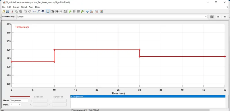
We can buil customised signal here by editing T value and Y value of every node. Here we have made this signal as per condition given.
On the other side of 'Thermistor' we have to put a 'Battery', 'Resistor' & 'Voltage Sensor'. '+' port of 'Battery' will be connected to '+' port of 'Thermistor' and '-' port of 'Battery' will go to '-' port of 'Voltage Sensor'. '+' pot of 'Voltage Sensor' will be connected to '+'port of 'Resistor' and also '-' port of 'Thermistor'. And '-' port of 'Resistor' will be connecdyed to '-'port of 'Voltage Sensor'. Make sure a 'Electrical Reference' and a 'Solver Configuration' are connected to common '-' port of electrical part.
Next Take a 'Switch' block and connect its 2nd input port to V port of 'Voltage Source'. Then connect two different 'Constant' block to input port 1 & 3 of 'Switch' block. Make sure valu of two 'Constant' block must be different(Here we are using value '1' for indicating 'ON' and '0' for indicating 'OFF'). A 'Scop' block and a 'Display' block will be connected to out put port of 'Switch' block to show the how 'ON' and 'OFF' are taking place with respect to time.
Make sure Threshold value must be as same as output value of 'Voltage Sensor'.
So the final model will be-
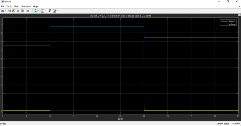
So from the reasult we can say that system is working properly as per condition. From 10 sec. to 30 sec. value of switch is 1. That means for that time period switch is on and other time switch is off.
Simulink file given below of this model-
https://drive.google.com/file/d/1ER_GF1T3Ri5l8QfMFkDP9oFm48tju0qt/view?usp=sharing