Week -2
PART 1
AIM
To make a Simulink model of Doorbell using solenoid block and to observe the physical movement of the plunger.
THEORY
Solenoid
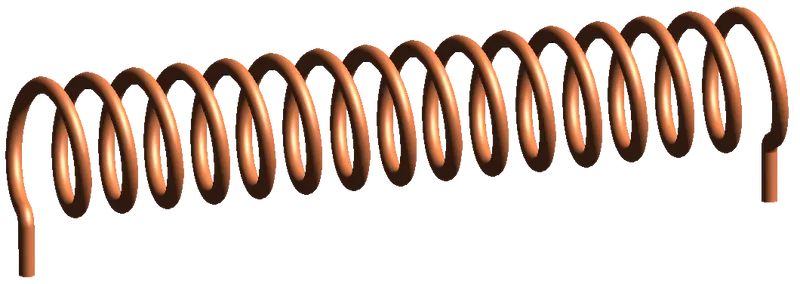
A Solenoid is a device comprised of a coil of wire, the housing and a moveable plunger (armature). When an electrical current is introduced, a magnetic field forms around the coil which draws the plunger in. More simply, a solenoid converts electrical energy into mechanical work. The coil is made of many turns of tightly wound copper wire. When an electrical current flows through this wire, a strong magnetic field/flux is created. The housing, usually made of iron or steel, surrounds the coil concentrating the magnetic field generated by the coil. The plunger is attracted to the stop through the concentration of the magnetic field providing the mechanical force to do work.
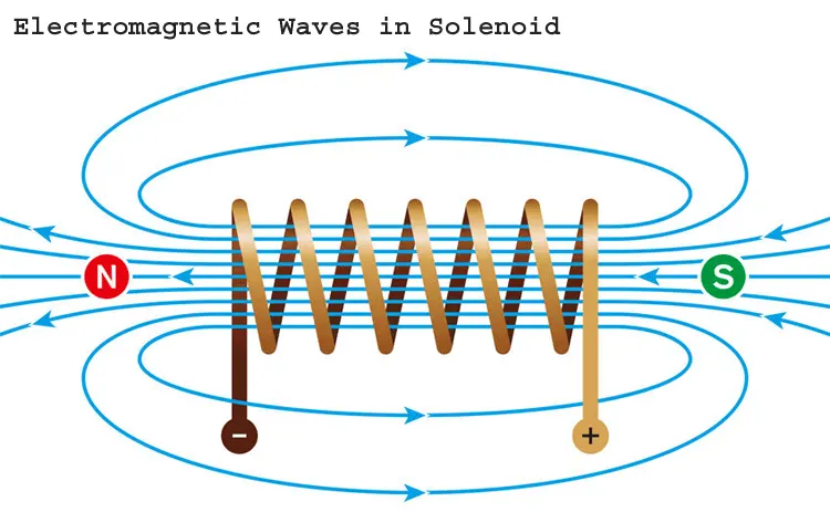
`B = underset(0)(mu) (NI)/l`
Where B = Solenoid magnetic flux density
`underset(0)(mu)` = Magnetic constant
N = Number of turns
I = Current
`l` = Length of solenoid
Electric Bell
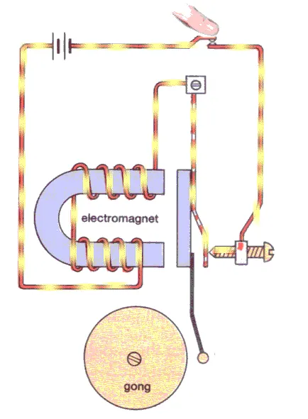
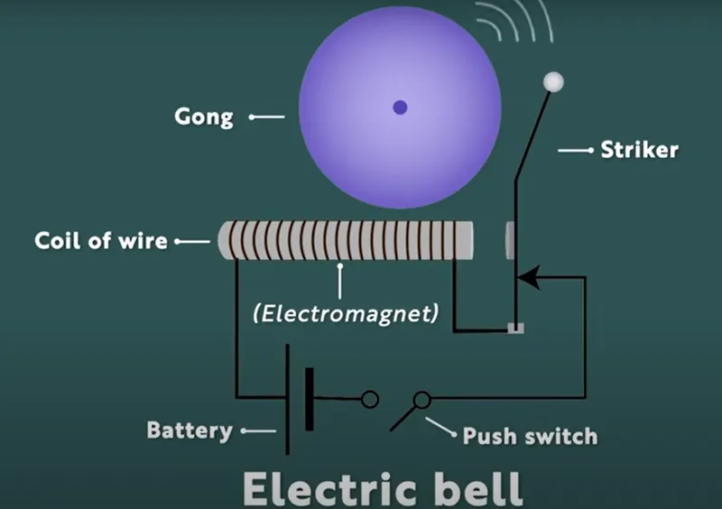
An electric bell is a mechanical or electronic bell that functions by means of an electromagnet. When an electric current is applied, it produces a repetitive buzzing, clanging or ringing sound.
Components:
- A coil of wire wound over an iron piece that form the electromagnet
- An iron strip which has a hammer attached to it which is joined to the wire coil.
- A contact screw through which is attached to the iron strip.
- A Battery which connects the wire coil and the contact screw
- A Switch in the middle of the circuit.
Working:
- When the switch of the bell is ON an electric current flows through the coil of wire which makes the iron piece attached to it act as an electromagnet
- As a result, the iron piece attracts the hammer towards itself. The hammer thus hits the bell and a sound is produced.
- As the hammer move towards the iron piece, it moves away from the contact screw which breaks down the circuit.
- As the circuit breaks the wire coil stops receiving any current which makes the electromagnet to lose its magnetic effect.
- As a result, the hammer falls back to its original position.
- Then as the hammer falls back, the iron strip again comes in contact with the contact screw and the circuit gets completed.
- This again turns the iron piece into an electromagnet and the whole process continues until the bell is switched OFF. This results in the continuous ringing of the bell.
BLOCKS USED
- Pulse Generator: To generates square wave pulses at regular intervals. The block waveform parameters, Amplitude, Pulse Width, Period, and Phase delay, determine the shape of the output waveform.
- Switch: Block that controls the current flow in the circuit, controlled by an external physical signal. If the external physical signal PS is greater than the value specified in the threshold parameter, then the switch is closed, otherwise the switch is open.
- Battery: Block with positive and negative terminal to generate electric flow to the circuit according to the given parameter.
- Solenoid: It is an electro magnetic device comprised of a coil of wire, the housing and a moveable plunger represents the electrical characteristics.
- Ideal Translational Motion Sensor: It represents a device that converts an across variable measured between two mechanical translational nodes into a control signal proportional to velocity or position.
- Scope: To generate plot of the output
- Mechanical Translational Reference: It represents a reference point, or frame, for all mechanical translational ports.
- Electrical Reference: It represents an electrical ground.
PROCEDURE
- Start
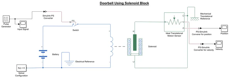
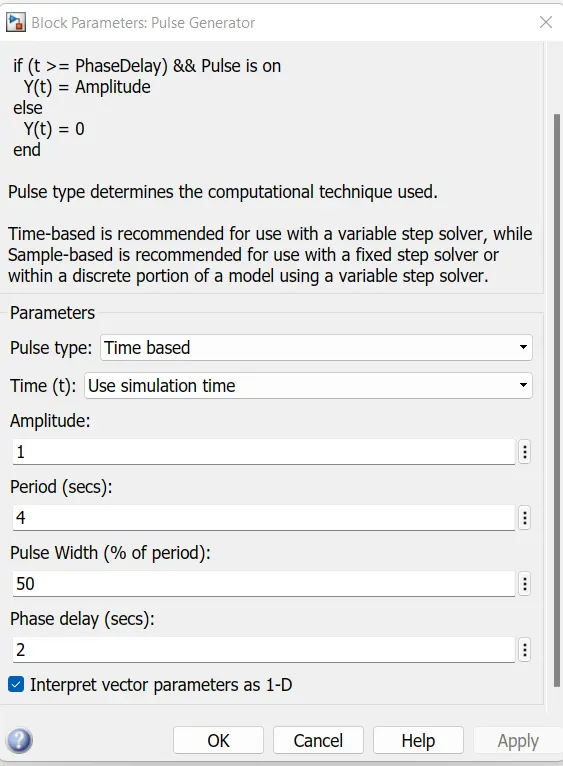
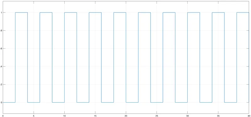
- Create Pulse Generator block for the input signal and change the parameters as per our need, here amplitude as 1, period as 4sec, phase delay as 2secs, pulse width as 50%
- Pass these signal through simulink-ps converter and then to switch
- Connect one end of the switch to positive terminal of the battery and other end to the electrical part of the solenoid
- Negative terminal of the battery is connected to the other end of the Solenoid's electrical part.
- R port of Solenoid's mechanical part is connected to the R port port of Ideal Translational Motion Sensor
- C ports are connected to the Mechanical Translational reference
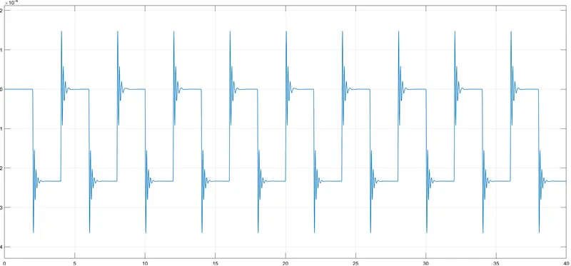
- Connect scopes to V and P port of Ideal Translational Motion Sensor to get the plot of Velocity and Position of the plunger respectively
- Connect Electrical reference and solver configuration.
- Run the Model
- Exit
MODEL
Input Parameter
Input Signal
RESULT
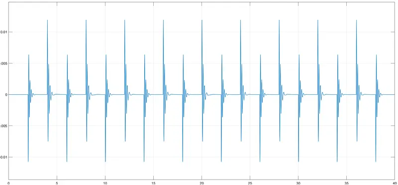
Position Of The Plunger
Velocity Of The Plunger
Simulink File
https://drive.google.com/file/d/1E0zK4EUvHHkIOtTaGsSG8eyKEc9OfLQb/view?usp=sharing
CONCLUSION
Simulink model of Doorbell using solenoid block has been made and observed the physical movement of the plunger.
REFERENCE
https://in.mathworks.com/help/simulink/index.html
https://www.vedantu.com/physics/working-of-electric-bell
https://www.tlxtech.com/articles/solenoid-101-what-is-a-solenoid
PART 2
AIM
To make model using a thermistor to sense the temperature of a heater & turn on or turn off the fan as per the given conditions.
THEORY
A thermistor (or thermal resistor) is a type of resistor whose resistance is strongly dependent on temperature, more so than in standard resistors. Although all resistors’ resistance will fluctuate slightly with temperature, a thermistor is particularly sensitive to temperature changes. It is made of metallic oxides, pressed into a bead, disk, or cylindrical shape and then encapsulated with an impermeable material such as epoxy or glass.
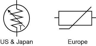
There are two types of thermistors:
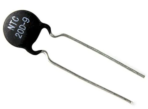
- Negative Temperature Coefficient (NTC)
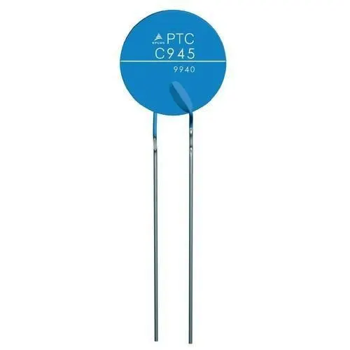
- Positive Temperature Coefficient (PTC)
Negative Temperature Coefficient (NTC)
NTC Thermistors are non-linear resistors, which alter their resistance characteristics with temperature. The resistance of NTC will decrease as the temperature increases. With an NTC thermistor, when the temperature increases, resistance decreases. Conversely, when temperature decreases, resistance increases. This type of thermistor is used the most. They are primarily used as resistive temperature sensors and current-limiting devices. The temperature sensitivity coefficient is about five times greater than that of silicon temperature sensors (silistors) and about ten times greater than that of resistance temperature detectors (RTDs). NTC sensors are typically used in a range from −55 to +200 °C.
Positive Temperature Coefficient (PTC)
The PTC thermistor is one type of resistor including a positive temperature coefficient, which means the temperature will be increased once the resistance increases. So the main relationship between resistance (R) & temperature (T) is linear. Most PTC thermistors are designed with doped polycrystalline ceramic that includes BaTiO3 (barium titanate) & other compounds. These materials have the property that is, at a particular critical temperature, the resistance will be increased suddenly. The working principle of the PTC thermistor mainly depends on the change within resistance because of a change within the temperature. Once the temperature increases, then resistance will be increased.& temperature reduces then resistance will be decreased. So in this type of thermistor, both the resistance & temperature are directly proportional.
Uses Of Thermistors
Thermistors have a variety of applications. They are widely used as a way to measure temperature as a thermistor thermometer in many different liquid and ambient air environments. Some of the most common uses of thermistors include:
- Digital thermometers (thermostats)
- Automotive applications (to measure oil and coolant temperatures in cars & trucks)
- Household appliances (like microwaves, fridges, and ovens)
- Circuit protection (i.e. surge protection)
- Rechargeable batteries (ensure the correct battery temperature is maintained)
- To measure the thermal conductivity of electrical materials
- Useful in many basic electronic circuits (e.g. as part of a beginner Arduino starter kit)
- Temperature compensation (i.e. maintain resistance to compensate for effects caused by changes in temperature in another part of the circuit)
- Used in wheat stone bridge circuits
Working
The working principle of a thermistor is that its resistance is dependent on its temperature. We can measure the resistance of a thermistor using an ohm meter. If we know the exact relationship between how changes in the temperature will affect the resistance of the thermistor – then by measuring the thermistor’s resistance we can derive its temperature. How much the resistance changes depends on the type of material used in the thermistor. The relationship between a thermistor’s temperature and resistance is non-linear.
BLOCKS USED
- Signal Builder: To create signals. The Signal Builder block allows to create interchangeable groups of piecewise linear signal sources and use them in a model. It creates signals and define the output waveforms.
- PS-Simulink Converter: To convert physical signal to simulink signal
- Controlled Temperature Source: To maintain specified temperature difference across the source regardless of the heat flow consumed by the system.
- Thermal Reference: To represents a thermal reference point, that is, a point with an absolute zero temperature, with respect to which all the temperatures in the system are determined.
- Thermistor: To represents an NTC thermistor relation between temperature and resistance.
- Battery: Block with positive and negative terminal to generate electric flow to the circuit according to the given parameter.
- Resistor: Block to limits or regulates the flow of electrical current in an electronic circuit.
- Voltage Sensor: To measure the voltage across the circuit and is connected in parallel. It converts voltage measured between two points of an electrical circuit into a physical signal proportional to the voltage.
- Electrical Reference: It represents an electrical ground.
- Constant: To generate a constant output value
- Simulink-PS Coverter: To convert simulink signal to physical signal.
- Switch: It specify the condition under which the block passes the first input by using the Criteria for passing first input and threshold parameters. The first and third inputs are data input. The second input is a control input.
- Scope: The Scope block displays its input with respect to simulation time.
- Solver Configuration: The Solver Configuration block specifies the solver parameters that your model needs before you can begin simulation. Each Simscape block diagram requires exactly one Solver Configuration block to be connected to it.
PROCEDURE
- Start
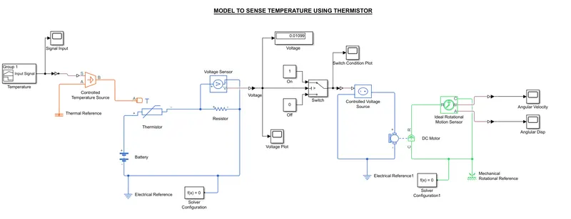
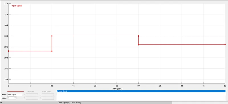
- Create a signal block with temperature values in Kelvin as per the paramters given.
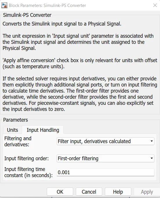
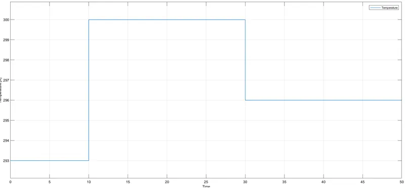
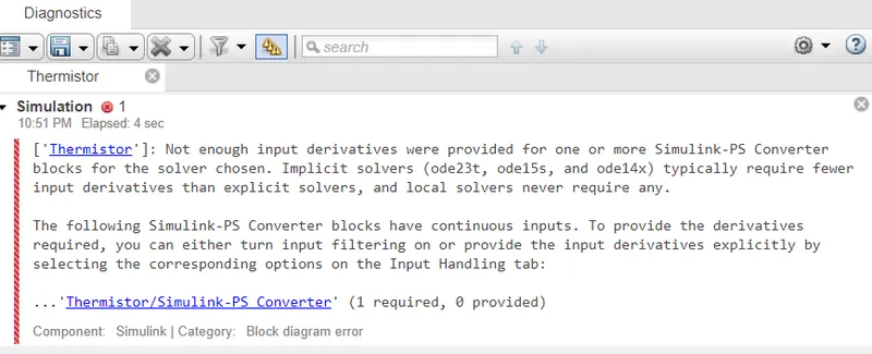
- Pass these signal through Simulink-ps converter where the unit has to be changed into K and In 'Input Handling' under 'Filtering and derivatives' choose 'filter inputs, derivatives calculated', because the thermal blocks will accept only kelvin by default
- These signal is then connected as the source to controlled temperature source which is then connected to Thermistor block.
- A Resistor Block is connected in series across the Thermistor.
- A Voltage Sensor is connected across the Resistor in parallel and a Scope and Display is given to get the plot and voltage value respectively.
- A Battery is given where the positive terminal is connected to ppositive port of Thermistor block and negative terminal is connected to negative port of the Resistor block.
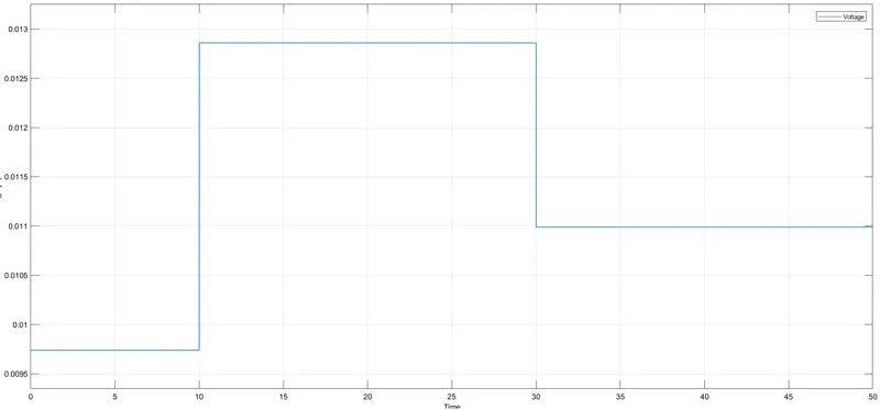
- Signal from the voltage sensor is passed to 2nd port(control port) of the switch.
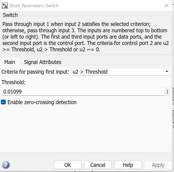
- Two Constant Blocks with Value 1 and 0 are connected to 1st port and third port (data ports) of the switch respectively.
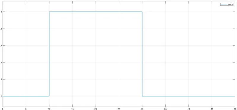
- If the threshold value satisfies the condition then signal will pass through 1st port and displays value as 1 or else will pass through 3rd port and displays value as 0.
- Signal from the Switch is given as source to Controlled Voltage Source which is then connected to the respective ports of electrical part of the Dc Motor.
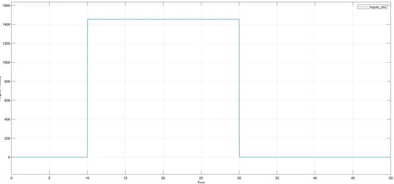
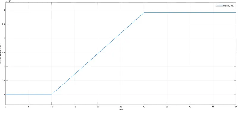
- The mechanical part of the DC Motor is connected to Ideal Rotational Motion sensor to measure the Angular Velocity and Angular Displacement.
- The Angular Velocity and Angular Displacement can be seen by connecting two scopes to W & A port respectively.
- Mechanical Rotational Reference, Thermal Reference, Electrical Reference, Solver configuration have been connected at respective areas.
- Run the Simulation
- Exit
MODEL
Input Signal
RESULT
Temperature
Voltage
Switch
Angular Velocity
Angular Displacement
Simulink File
https://drive.google.com/file/d/1M07LTsyXn2QAeLBk1sb2QU9-wCS5otEA/view?usp=sharing
ERRORS OCCURED
Error
Action To Overcome Error
Block parameters of Simulink-PS converter has been changed. In 'Input Handling' under 'Filtering and derivatives' choose 'filter inputs, derivatives calculated'.
Input Handling ---> Filtering and derivatives ---> filter inputs, derivatives calculated
CONCLUSION
Model using a thermistor to sense the temperature of a heater & turn on or turn off the fan has been made.
REFERENCE
https://www.elprocus.com/ptc-thermistor/
https://eepower.com/resistor-guide/resistor-types/ntc-thermistor/