Week -2
AIM 1
Make a Simulink model of Doorbell using solenoid block
THEORY
A doorbell is a signalling device typically placed near a door to a building's entrance. When a visitor presses a button the bell rings inside the building, alerting the occupant to the presence of the visitor. Although the first doorbells were mechanical, activated by pulling a cord connected to a bell, modern doorbells are electric, operated by a pushbutton switch.
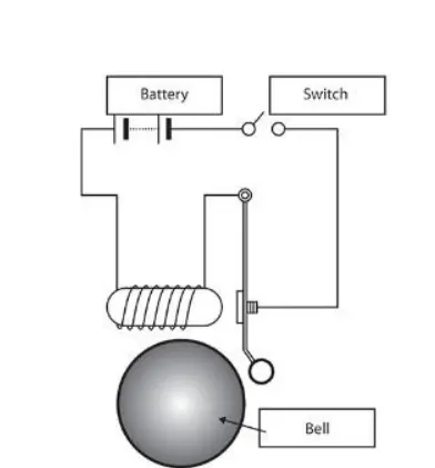
Solenoid: The solenoid is a coil of wire, and the plunger is made of soft iron. The magnetic field is formed around the coil when an electric current passes through it and draws the plunger in. We can say that the solenoid is responsible for converting electrical energy into mechanical work.
The basic components used to make doorbell in Simulink are:
- Pulse generator: The Pulse Generator block generates square wave pulses at regular intervals. The block waveform parameters, Amplitude, Pulse Width, Period, and Phase delay, determine the shape of the output waveform.
- Battery
- Switch
- Electrical reference: The Electrical Reference block represents an electrical ground. Electrical conserving ports of all the blocks that are directly connected to ground must be connected to an Electrical Reference block. A model with electrical elements must contain at least one Electrical Reference block.
- Solenoid: The solenoid is modeled as an inductance whose value L depends on the plunger position x.
- Ideal translational motion sensor: The Ideal Translational Motion Sensor block represents a device that converts an across variable measured between two mechanical translational nodes into a control signal proportional to velocity or position.
- Mechanical translational reference: The Mechanical Translational Reference block represents a reference point, or frame, for all mechanical translational ports. All translational ports that are rigidly clamped to the frame (ground) must be connected to a Mechanical Translational Reference block.
OBJECTIVE
- Create a situation where the switch is closed for 2 seconds and then released.
- Observe the physical movement of the plunger.
BLOCK DIAGRAM

EXPLANATION
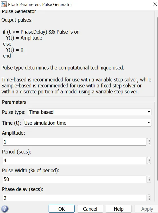
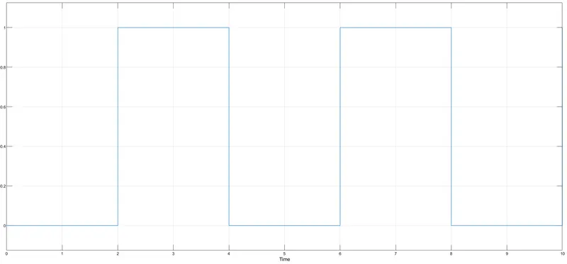
- Pulse generator block is used to generate square wave pulse at regular intervals. Here amplitude of 1 is given as default with period of 4, pulse width of 50% of period and phase delay of 2 seconds is given as per our requirement.
- Simulink to PS converter is used to convert the unitless Simulink input signa, to a physical signal.
- Signal from the Simulink-PS converter is connected to the switch.
- One of the leads of switch is connected to the positive terminal of battery to provide electrical power supply.
- Other terminal of the battery is connected to the solenoid and the other end of solenoid to the switch thus closing the circuit.
- Electrical reference is provided to give electrical grounding. A model with electrical elements must contain at least one electrical reference block.
- Solver configuration is also provided as the block specifies the solver parameters that your model needs before you can begin simulation.
- In the solenoid block, R and C are two variables which represents the plunger and fixed point respectively.
- Now this R is connected to the R of ideal translational motion sensor block, which sense the position of the plunger in the solenoid block and gives output.
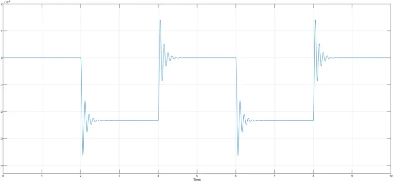
- In ideal translational motion sensor, V and P are the outputs which measures the velocity and position of plunger respectively. As our requirement is to identify the position, output from P is only taken and is connected to the PS-Simulink converter which converts physical signal to Simulink output signal. This signal is collected using scope block for generating the graph for the change in position of the plunger from port P of ideal translational motion sensor block.
- Now C in the ideal translational motion sensor block represents the mechanical translational conversion port which means that the mechanical process starts from R and ends at C and again from R to C and cycle goes on. So, C in the ideal translational motion sensor block is connected to a mechanical translational reference block which represents a reference point or frame for all mechanical translational ports.
RESULT
Input signal from pulse generator:
Output signal from the Ideal Translational Motion sensor calculating the position of plunger with respect to time:
CONCLUSION
- Simulink model of doorbell is created using solenoid.
- Physical movement of plunger is noted and plotted in graph.
- Situation is created where the switch is closed for 2 seconds and then released.
AIM 2
Block diagram of thermistor to sense the temperature of a heater & turn on or turn off the fan
THEORY
Thermistor: A thermistor is a type of resistor whose resistance is strongly dependent on temperature, more so than in standard resistors. Thermistor don’t work well with extreme temperatures at a certain point. They are precise when they are used within a limited temperature range.
The basic components used to make thermistor in Simulink are:
- Signal Builder block: It is used such a way that we can create our own signals.
- Controlled temperature source: The Controlled Temperature Source block represents an ideal source of thermal energy that is powerful enough to maintain specified temperature difference across the source regardless of the heat flow consumed by the system.
- Thermal reference: The Thermal Reference block represents a thermal reference point, that is, a point with an absolute zero temperature, with respect to which all the temperatures in the system are determined.
- Thermistor block: It is a type of resistor whose resistance depends upon temperature.
- Voltage Sensor: The Voltage Sensor block represents an ideal voltage sensor, that is, a device that converts voltage measured between two points of an electrical circuit into a physical signal proportional to the voltage.
- Switch: The Switch block propagates one of two inputs to its output depending on the value of a third input, called the control input. If the signal on the control (second) input is greater than or equal to the Threshold parameter, the block propagates the first input; otherwise, it propagates the third input.
- DC Motor: Converts input electrical energy into mechanical motion.
- Ideal Rotational Motion sensor: The Ideal Rotational Motion Sensor block represents an ideal mechanical rotational motion sensor, that is, a device that converts an across variable measured between two mechanical rotational nodes into a control signal proportional to angular velocity or angle.
OBJECTIVE
Use a thermistor to sense the temperature of a heater & turn on or turn off the fan as per the below conditions:
Temperature source: 20 °C from 0 to 10 seconds, 27 °C from 10 to 30 seconds, 23 °C from 30 to 50 seconds
Fan conditions: ON if the temperature above 25 °C, OFF otherwise.
BLOCK DIAGRAM
EXPLANATION
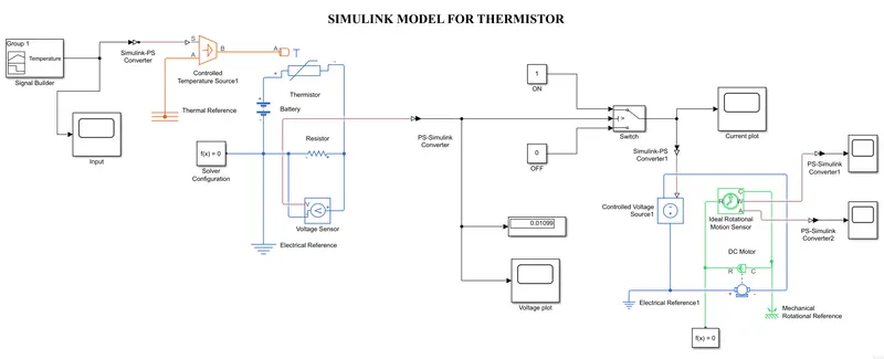
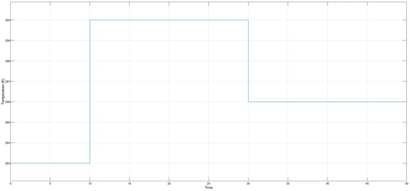
- Temperature input is provided to the system through a signal builder, so that we can provide our own required signals as our wish. As per the requirements in the question, temperature is 293 K for a time between 0-10 seconds, 300 K for a time period of 10-30 seconds and 296 K for a time period of 30-50 seconds.
- Simulink-PS converter is used to convert the input signal provided in the Simulink to physical signal. Input signal from the signal builder is plotted using scope block.
- Controlled temperature source is provided which is an ideal source for thermal network. The temperature difference is set by the physical signal port S. A positive temperature difference causes the temperature at port B to be greater than the temperature at port A. Port A is grounded using thermal reference with respect to which the temperature is measured. From port B it is connected to thermistor at port A which is the input for thermistor.
- The positive terminal of thermistor is connected to the positive terminal of battery and the negative terminal of battery is connected to the negative terminal of resistor. Positive terminal of resistor is connected to the negative terminal of thermistor thus closing the circuit.
- Voltage sensor is connected in parallel to the resistor as shown in the block diagram.
- This electrical circuit is grounded using electrical reference and a solver configuration is also added.
- From the voltage sensor, the output is the voltage which is obtained from port V and it is converted to Simulink output using PS-Simulink converter. The output thus obtained is displayed in display block and plotted in scope as well.
- Switch is connected from the PS-Simulink converter such that to make the fan run if the temperature is above 298 K. For this threshold value is calculated for 298K and is given as the threshold value for the switch. Thus, if the input voltage is more than threshold value, then it will make the switch to ON condition making the supply for the fan.
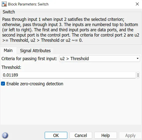
- The output from the switch is plotted in the scope block as shown in the block diagram.
- Again, a Simulink-PS converter is used to convert the Simulink input to physical signal so as to provide the input signal for the controlled voltage source so as to run the DC Motor.
- The rotation of DC motor is sensed using ideal rotational motion sensor and the output is provided in scope block.
- Mechanical rotational reference is provided as the reference for the DC motor as it involves rotational mechanical parts.
RESULT
Input signal from the signal builder:
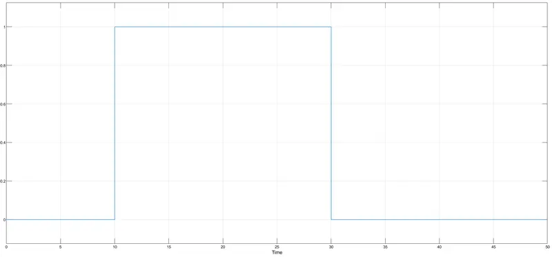
Output signal obtained from the switch:
CONCLUSION
- Thermistor block diagram is created using Simulink.
- Fan conditions: ON if the temperature above 25 °C, OFF otherwise is also obtained.