Week -2
DOORBELL STIMULATION USING SIMULINK
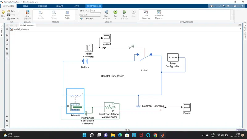
Simulink model explanation: -
- Pulse generator block
- DC Battery
- Switch block
- Solenoid block
- Ideal transitional motor sensor block
- Mechanical transitional reference
- Electrical reference block
- Scope
- PS-Simulink & Simulink-PS converter
Block diagram explanation: -
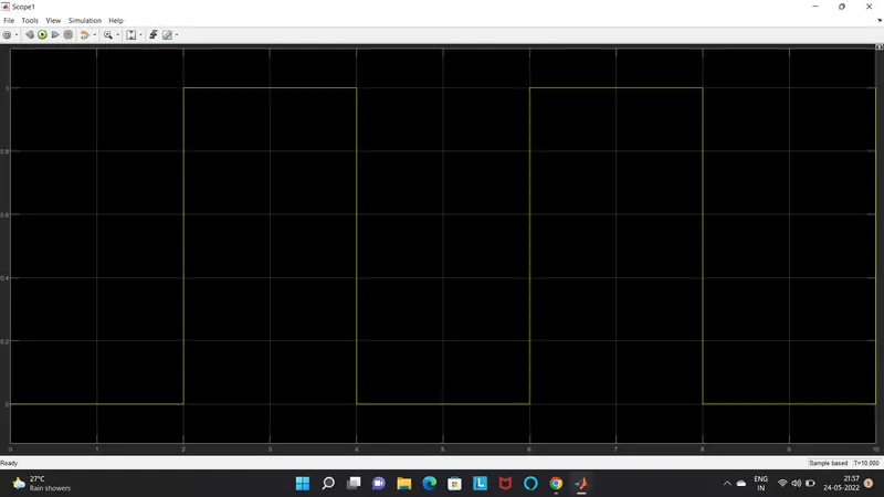
Pulse Generator is used to generate square wave pulses at regular interval of time. The block waveform parameters, amplitude, pulse width, period and phase delay, determines the shape of waveform. In our case switch is closed for 2 seconds and released. And set waveform parameters as follow,
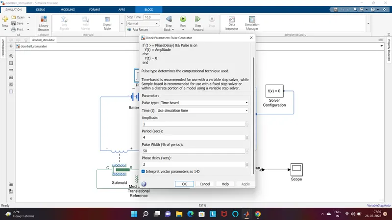
Then the pulse generator is then connected to Simulink-PS converter then that is connected to the Switch Block.
Switch Block is controlled by the external physical signal and if the external physical signal is greater than the switch is closed or else switch is open.
Then a DC battery is connected along with solenoid block, switch and electrical reference and a solver configuration to form a complete electrical circuit.
The R port of the solenoid is connected along with mechanical reference and R fort of ideal transitional sensor, to observe the movement of the plunger.
Then the sensor is connected to PS- Simulink convertor that convert the physical signal to the Simulink signal then connect to the scope
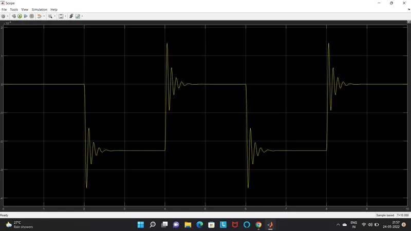
Scope is used to visualizing the plunger movement according to the change in voltage
Result
The output is visualized and we can reduce the vibration by increasing the damper coefficient and decreasing the spring constant
THERMISTOR
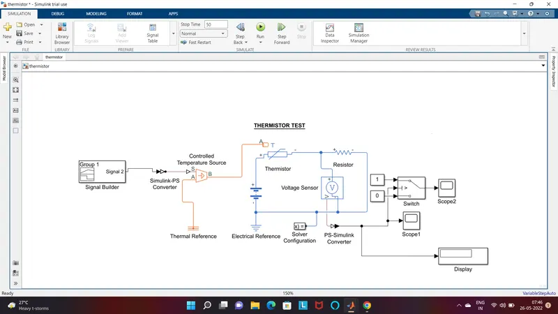
Simulink model explanation: -
- Signal Builder
- DC Battery
- Switch block for Fan
- Voltage Sensor
- Electrical Reference
- Resistor
- Thermistor
- Solver Configuration
- Scope
- PS-Simulink & Simulink-PS converter
- Thermal Reference
- Display
- Temperature Control Source
- Constant block
Block diagram explanation: -
We have one condition that the fan must ON if the temperature is above 25 Degree Celsius. For that initially run the program by using a constant block of value 298K. Then from the display we get the value of the voltage corresponding to temperature 25 degree
Signal builder is the block used to give signal according to the conditions of temperature with time. The temperature must be in kelvin then create the graph to generate the signal where x axis is time and y axis as temperature.
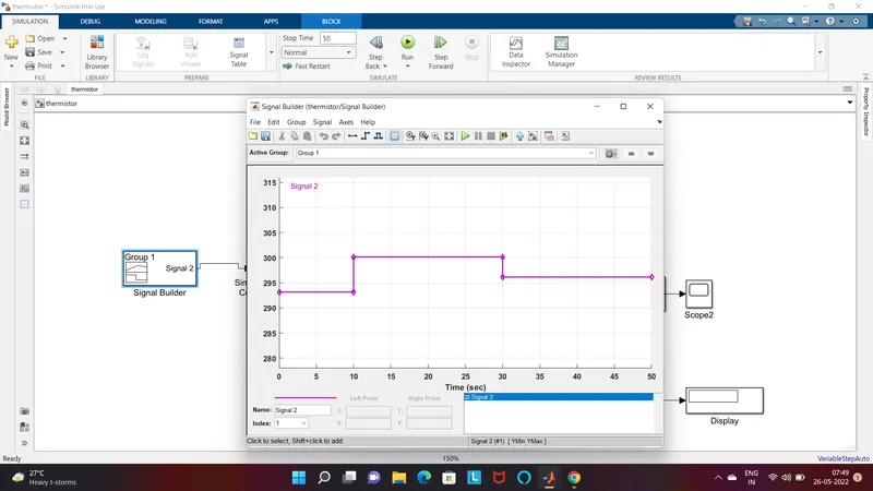
Simulink-PS converter converts the signal from the signal builder to physical signal.
Controlled Temperature Source is represent an ideal sourse of thermal energy that is powerfull enough tho maintain a specific temperature difference across source regardless of the heat flow consumed by the system. It is connected where S is the input point B is the output and A is connected to the thermal reference block
Thermistor is used to measure temperature coefficient of resistor that vary the resistance according to temperature value . The input of thermistor is at A were other two terminal used to connect battery, voltage sensor(voltage sensor converts the voltage measure between two points of an electrical circuit into physical signal proportional to the voltage), resistor, solver, electrical reference to form a closed circuit
From voltage sensor the output is converted in to Simulink signal then the connection go to the display , scope and the fan switch
RESULT
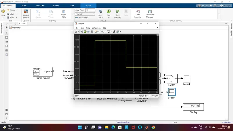
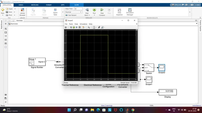
From 0-10 second fan is OFF because the temperature is 293k which is below 293k, after 10 second it goes to 300k, so fan will turn ON because temperature exceeds 298k after 30 second fan will turn OFF because temperature goes 296k less than 298k