Week -2
AIM
1. Make a Simulink model of Doorbell using solenoid block with the following details:
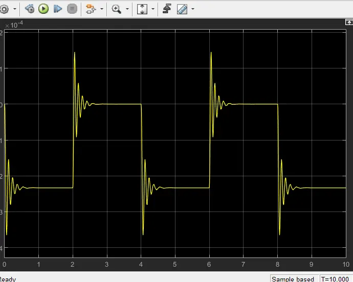
In the above arrangement, when the switch is closed the electromagnet receives electrical power from the battery and pulls the metal arm to hit the bell producing sound. Create a situation where the switch is closed for 2 seconds and then released. Observe the physical movement of the plunger.
2. Use a thermistor to sense the temperature of a heater & turn on or turn off the fan as per the below conditions:
Temperature source: 20 °C from 0 to 10 seconds, 27 °C from 10 to 30 seconds, 23 °C from 30 to 50 secondsFan conditions: ON if the temperature above 25 °C, OFF otherwise
OBJECTIVE
- Make a Simulink model of Doorbell using solenoid block.
- Use a thermistor to sense the temperature of a heater & turn on or turn off the fan
EXPLANATION
- FOR DOOR BELL USING SOLENOID BLOCK
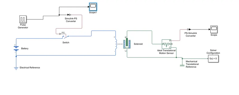
- For creating the bell simulation by using this blocks Battery, switch, Pulse generator, Simulink to PS converter, Solenoid, Ideal Translational Motion sensor, Electrical Reference, Mechanical translational Reference, PS Simulink converter, Solver configuration and Two Scope one for Plus Generator and Another for output.
- First we connect the battery positive side to switch and then connect the switch to solenoid positive side.
- And connect the negative side of the solenoid to battery and connect the reference to the electric circuit.
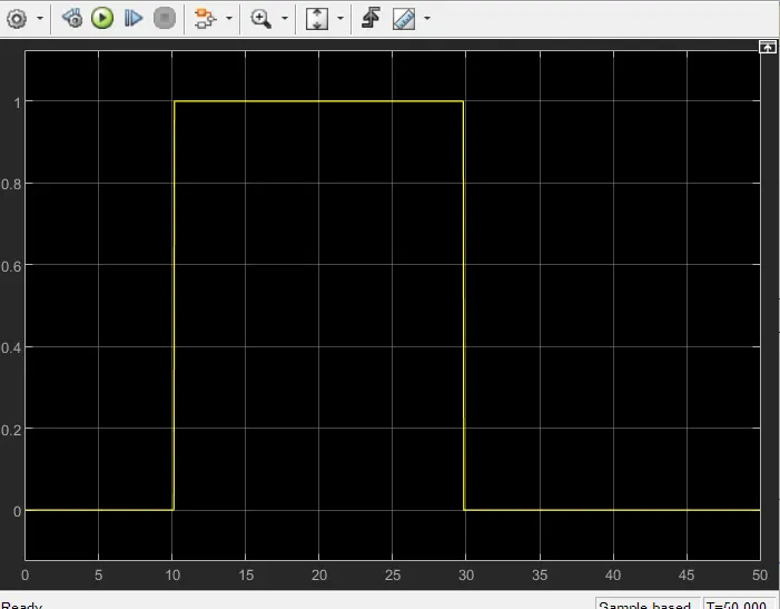
- In pulse generator we change the Periods sec as 4 because are aim to ring the bell for 2 sec and released. So here we give 4 and Pulse width as 50% because this pulse width it will take 50 % data of Period so the value is 2.
- We connect the scope to check the on and off time. The image is
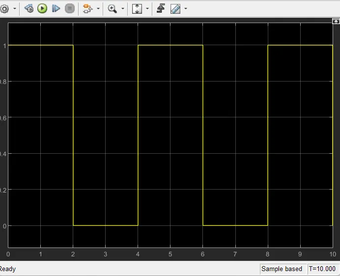
- By observing the plot from the scope we can able to get to the conclusion that the give data is correct and the system is on and off for specified time.
- Here in pulse generator is not producing the Physical signal so we can’t connect the pulse generator output to switch so we use the “ Simulink PS converter”. We connect the output of Pulse generator to simulink PS converter and connect the simulink PS converter to switch.
- One side of solenoid is Electrical and another side is mechanical.
- The another side is have the R and C. There we have a Translational Mechanical movement to get the value of the mechanical movement we use the ‘Ideal translational motion sensor’.
- We connect R in the solenoid and sensor and C in the solenoid and the sensor after that we connect the mechanical reference in the end.
- Here in the ideal translational motion sensor we have P that is the output signal but this signal is a Physical signal so we have to convert this by using the PS to simulink converter and connect them with the scope to observe the result.
- We use the solver configuration is because in this system is have some coding that because is the physical component it have some code so we use the this solver configuration to sort out this error.
- FOR USING THERMISTOR TO SENSE THE TEMPERATURE OF A HEATER & TURN ON OR TURN OFF THE FAN.
- From the reference of the given website from the FAQ came to understand the required blocks and from the design display there I can understand and make some changes for this system.
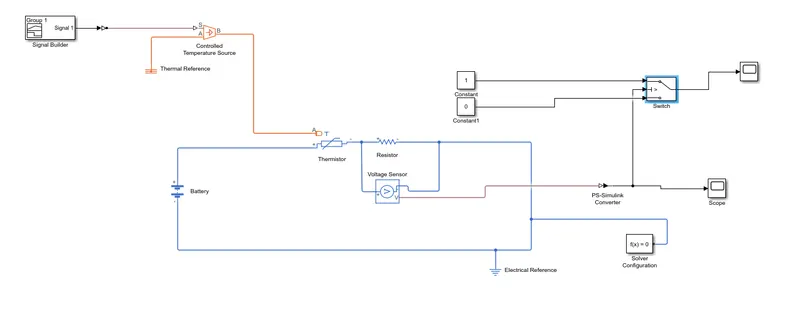
- For creating this simulation this simulations are required some blocks those are Signal builder, controlled temperature source , PS- simulink converter, Thermal reference, Thermistor, Battery, Resistor, voltage Sensor, Electrical reference, Simulink- PS converter, Solver configuration, Two scope, two constant and Switch.
- For PS-Simulink block we have made a change in Input handling there in filtering and derivatives. Default values is provide signals and we change that into Filter inputs, derivatives calculated. We made change because that the input in this case is vary for 50 sec so we make a change without this change the PS simulink converter give only one first value it cause error.
- We connect the signal builder with changed PS- simulink converter and we connect this with controlled temperature source.
- We connect thermal reference to the controlled temperature source in A port and output from this is connect with thermistor port A.
- Battery positive side is connected with thermistor positive side.
- The another side of thermistor is connected with resistor adjacently.
- The voltage sensor is connected parallel to resistor.
- Battery another side is connected with resistor. Here we connect the electrical reference here in the circuit and solver configuration also.
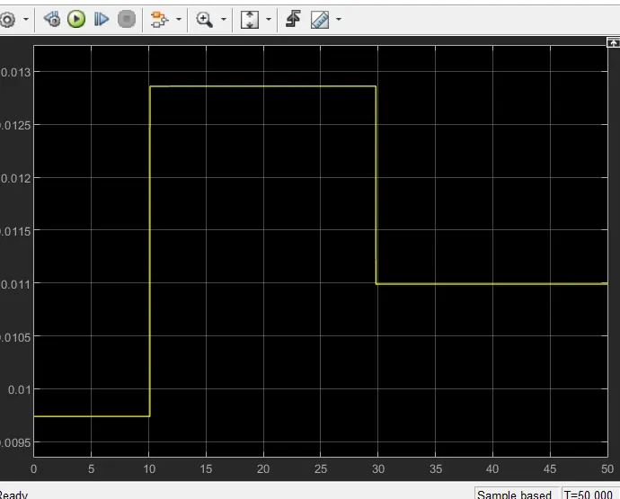
- The output from the voltage sensor is connected with PS-Simulink converter and this output is connected with scope.
- Based on the voltage this system is on and off. So the output after the PS simulink converter is connected with switch. In that switch we made a change based on the voltage output.
- We gave a value in Threshold as 0.012 by means of result from the voltage sensor by the help of scope.
- For switch on and off we use the constant blocks and give them values as 1 and 0.
- Then the results came.
CIRCUIT IMAGE
FOR FIRST QUESTION
FOR SECOND QUESTION
RESULT IMAGE
FOR FIRST QUESTION
FOR SECOND QUESTION
RESULT FROM VOLTAGE SENSOR
For the given question we make a simulation successfully.