Week -2
Aim:
- Make a Simulink model of Doorbell using solenoid block with the following details
- Use a thermistor to sense the temperature of a heater & turn on or turn off the fan as per the below conditions.
- Block diagram of Doorbell
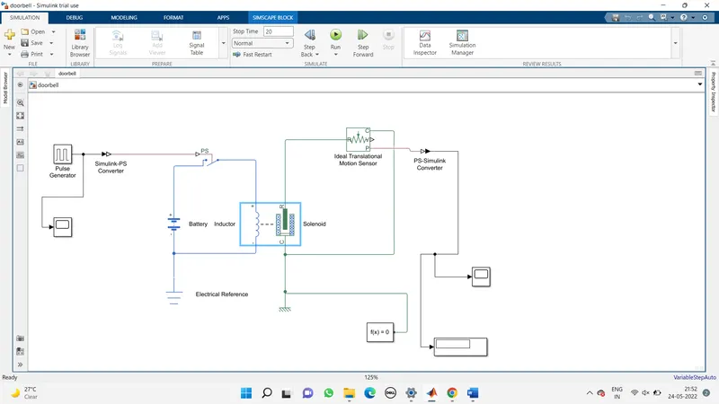
Explanation of block diagram used in model
- Pulse Generator.
- Simulink-PS Converter and PS- Simulink converter.
- PS switch
- Solenoid
- Solver Configuration
- Scope
- Mechanical and Electrical reference
- Ideal translational reference
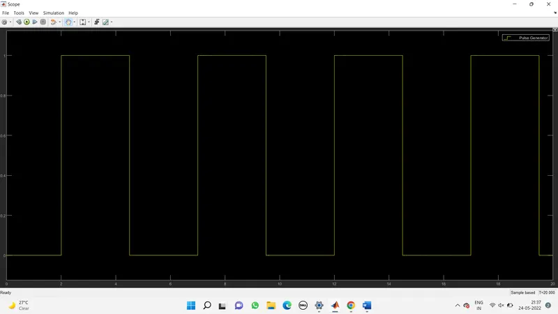
- Pulse generator is basically used to fed the input values to the model and one scope is been connected to the pulse so that we can see the input feeder is correct or not the conditions are satisfied or not
- Battery is used to give current source to the circuit as soon as the PS switch gets closed
- We used PS switch which is connected to the pulse generator through simulink PS converter as our PS switch is simscape model as per the given input to the pulse generator the ps witch will close the circuit at every 2 sec and again it will open the circuit.
- Solver configuration is must in simscape model to solve the model.
- solenoid is used to convert the electrical signals to mechanical output of the plunger ideal translational motion sensor is used to sense the plunger
- movement and gives the output pulse on the graph mechanical and electrical reference is also used to give a particular fixed or reference position in which respect to the other points been operated
- scope is used here to broadcast the output plot as per the plunger motions
Output
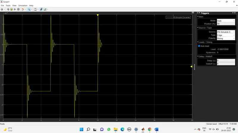
Result
In this plot we can see at every 2 seconds there is vibration in plots which shows that plunger moves down and hit the bell and hit the bell and bell is rang so our condition got satisfied
- Block diagram of thermistor:
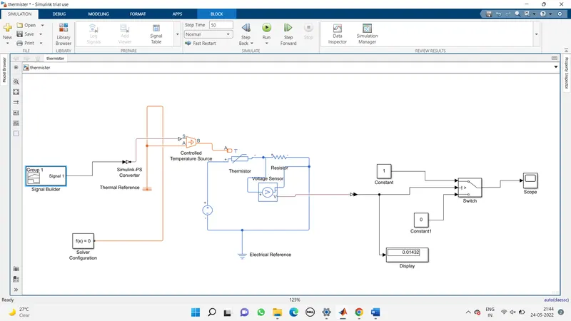
Explanation of block diagram used in this model:
- Signal Builder
- Simulink-PS and PS-Simulink converter
- Controlled Temperature source
- Solver Configuration
- Thermister
- Resister
- DC voltage source
- Voltage senser
- Electrical reference
- Display
- Scope, Switch , Constant
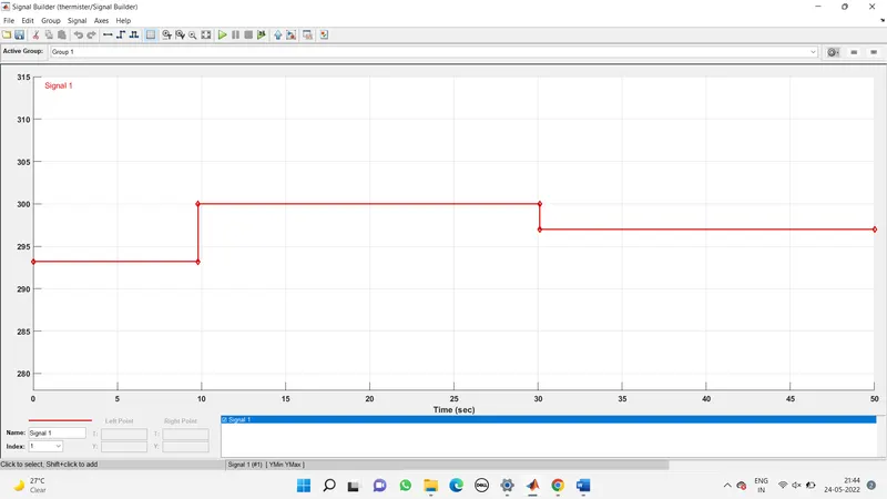
- First we used the signal builder to feed the given conditions of the heater at which the thermistor has to sense the temperature (i.e from 0 to 10 sec the temperature is 293 k ,from 10 to 30 sec the temperature is 300k and from 30 to 50 sec temperature is 298k)
- Then we used controlled temperature source which take the input values and translate it and feed to the the thermistor
- Thermistor sense the temperature which has been input in the system and gives output as per that
- Resistor and voltage sensor is used to pass the temperature output values to the switch and voltage sensor around resistor sense the voltage across it
- Dc voltage source supplies 12 v supply to the circuit
- As switch gets the threshold value greater than equal to constant then it on the fan at 298k.The 2 constant used in System is that if threshold value is greater than so it will give I value or it will give O value if it does not satisfies the given condition
- Scope is used to get desired output graph so we can determine the inputs and output are satisfied or not
Output
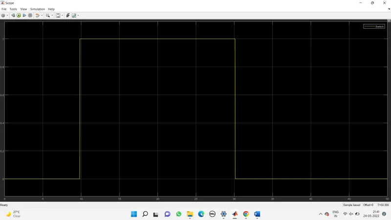
Result
Here by seeing the plot we can say that the fan gets on at 25 degree Celsius and for other all temperature and time value fan is switch off.
Fan is on between 10 to 30 sec at 25 degree Celsius