Week -2
Aim:-Make a Simulink model of Doorbell using solenoid block.
Here our objective is to make a Simulink model of the Doorbell using a solenoid block where ,when the switch is closed the electromagnet receives electrical power from the battery and pulls the metal arm to hit the bell producing sound. Also we hae a condition where the switch is closed for 2 seconds and then released. And we need to observe the physical movement of the plunger.
Simulink Model:-
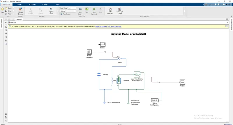
Blocks used:-
- Pulse Generator: - The Pulse Generator block generates square wave pulses at regular intervals. The block waveform parameters, Amplitude, Pulse Width, Period, and Phase delay, determine the shape of the output waveform.
- Simulink-PS Converter: - The Simulink-PS Converter block converts the input Simulink signal into a physical signal. Use this block to connect Simulink sources or other Simulink blocks to the inputs of a Simscape physical network.
- Switch: - The Switch block models a switch controlled by an external physical signal. If the external physical signal PS is greater than the value specified in the Threshold parameter, then the switch is closed, otherwise the switch is open.
- Battery: - The Battery block implements a generic dynamic model that represents the most popular types of rechargeable batteries.
- Solenoid: - The Solenoid block represents the electrical characteristics and generated force for the solenoid
- Solver Configuration: - Each physical network represented by a connected Simscape block diagram requires solver settings information for simulation. The Solver Configuration block specifies the solver parameters that your model needs before you can begin simulation.
- Ideal Translation Motion Sensor: - The Ideal Translational Motion Sensor block represents a device that converts an across variable measured between two mechanical translational nodes into a control signal proportional to velocity or position.
- Scope: - Display signals generated during simulation.in simple word display graph with respect to time.
Expalnation:-
- Firstly, the pulse generator is block is used to give signal inputs like amplitude, pulse width, period and phase delay to determine the shape of the output length. Scope is used to see the graph of wavelength.
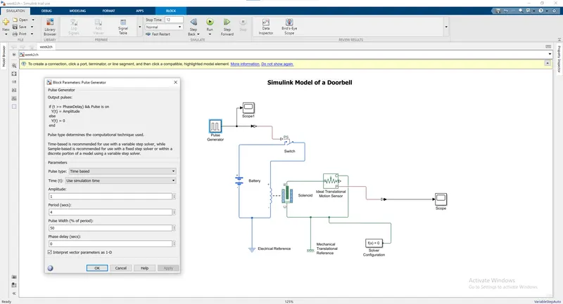
- After that Simulink-PS Converter is used to convert signal input to physical system and send to the switch block.
- To complete the circuit the battery, switch and solenoid block are used and connect to each other. The electric reference is used as a ground. All systems are connected in series. The solver configuration block is used to specify the solver parameter.
- The mechanical part of solenoid (clapper) is connected with ideal translation motion sensor because the motion of clapper is translation and for ground the mechanical translation reference is used.
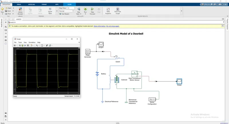
- The scope is connected to an ideal translation motion sensor to see the output graph of plunger motion. The output is as follows,
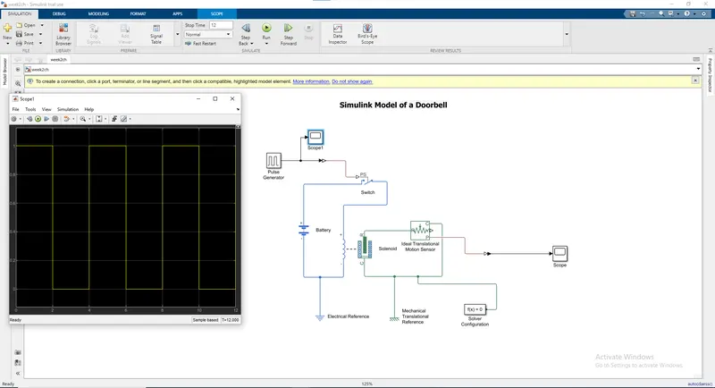
6.The below graph shows or rather depicts the motion of the plunger , the parameter of the solenoid has been optimized so as to obtain a profile same as the the input signal.(The damping value inside the solenoid has been changed to 10).
Objective 2:-
Aim:-Use a thermistor to sense the temperature of a heater & turn on or turn off the fan.
Here our objective is to use a thermistor in order to sense the temperature of a heater and turn on or turn of the fan according to the given condition i.e.
Temperature source: 20 °C from 0 to 10 seconds, 27 °C from 10 to 30 seconds, 23 °C from 30 to 50 seconds
Fan conditions: ON if the temperature above 25 °C, OFF otherwise.
Simulink Model:-
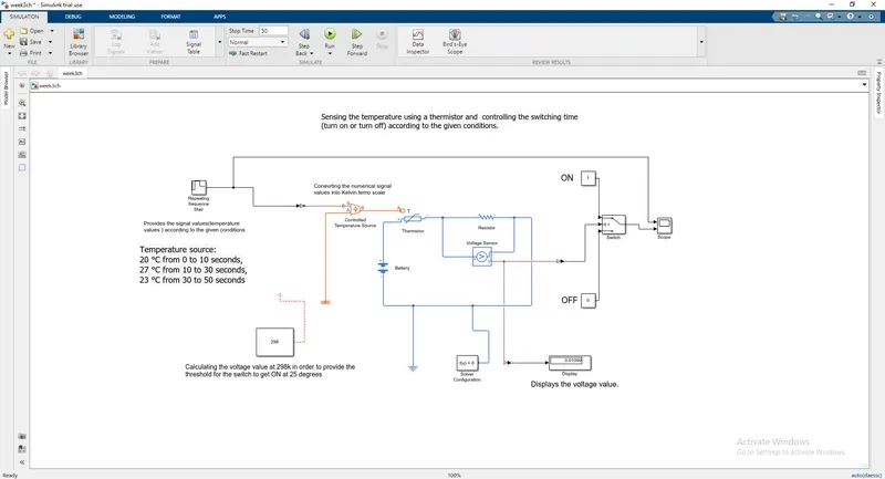
1.)The temperature values are provided as the inputs but the point that has to be taken in note here is that the control temperature sorcu provides values to the thermistor in Kelvin scale so in the input itself we have to change the signal values to temperature values in Kelvin.That is depicted below.
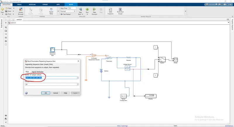
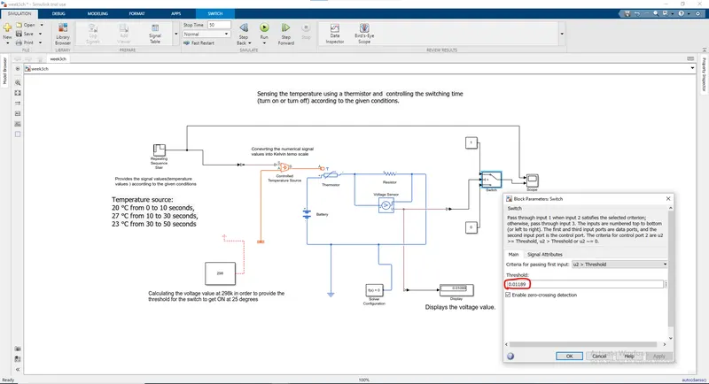
2.Based on the given condition that the fan should be turned on for temperature equal to and above 25 degrees(i.e.298K) we calculate the voltage drop in the circuit using the voltmeter and then provide that value as threshold for the switch which will let it turn ON at the required temperature of 25degrees and above.
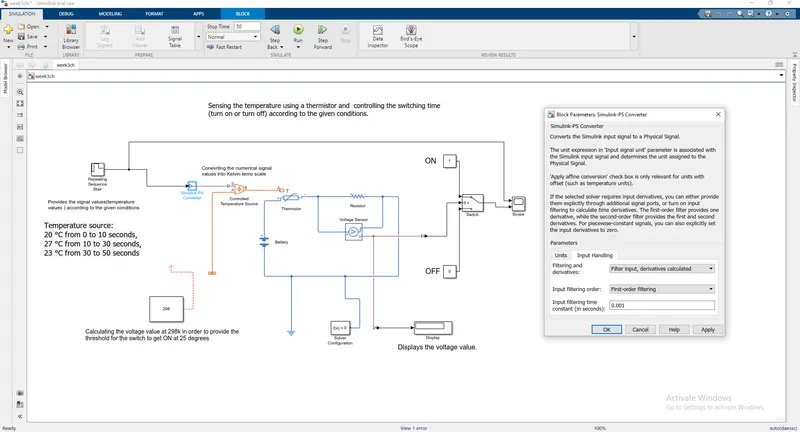
3.The final thing what we did in order to obtain a smooth graph of profile of the temperature we changed the parameter of filtering and derivatives to filtered inputs and derivatives calculated that will provide the tempurature value not as discrete values but as continuous values that will vary with a smooth gradient.
Blocks Used:-
- Signal Builder: - The Signal Builder block allows you to create interchangeable groups of piecewise linear signal sources and use them in a model. You can quickly switch the signal groups into and out of a model to facilitate testing. In the Signal Builder window, create signals and define the output waveforms.
- Simulink-PS Converter: - The Simulink-PS Converter block converts the input Simulink® signal into a physical signal. Use this block to connect Simulink sources or other Simulink blocks to the inputs of a Simscape physical network.
- Controlled Temperature Source: - The Controlled Temperature Source block represents an ideal source of thermal energy that is powerful enough to maintain specified temperature difference across the source regardless of the heat flow consumed by the system.
- Thermal Reference: - The Thermal Reference block represents a thermal reference point, that is, a point with an absolute zero temperature, with respect to which all the temperatures in the system are determined.
- Thermistor: - The Thermistor block represents an NTC thermistor which senses the temperature with respect to time.
- Battery: - The Battery block implements a generic dynamic model that represents the most popular types of rechargeable batteries.
- Voltage Sensor: - The Voltage Sensor block represents an ideal voltage sensor, that is, a device that converts voltage measured between two points of an electrical circuit into a physical signal proportional to the voltage.
- Electrical Reference: - The Electrical Reference block represents electrical ground. Electrical conserving ports of all the blocks that are directly connected to the ground must be connected to an Electrical Reference block. A model with electrical elements must contain at least one Electrical Reference block.
- Solver Configuration: - Each physical network represented by a connected Simscape block diagram requires solver settings information for simulation. The Solver Configuration block specifies the solver parameters that your model needs before you can begin simulation.
- PS-Simulink Convertor: - The PS-Simulink Converter block converts a physical signal into a Simulink output signal. Use this block to connect outputs of a Simscape physical network to Simulink scopes or other Simulink blocks.
- Switch: - The Switch block passes through the first input or the third input signal based on the value of the second input. The first and third inputs are data input. The second input is control input. Specify the condition under which the block passes the first input by using the Criteria for passing first input and Threshold parameters.
- Constant: - The Constant block generates a real or complex constant value signal. Use this block to provide a constant signal input.
- Display: - The Display block shows the value of the output data. You can specify the frequency of the display. For numeric output data, you can also specify the format of display.
- Scope: - Display signals generated during simulation.in simple word display graph with respect to time.
The Explanations are provided along with the screenshots of the model given above.
At the end of system scope is connected to see output for fan on or off. We run the simulation for 50 sec because we take time limit in signal builder as 50 sec. So, we can get the following output,
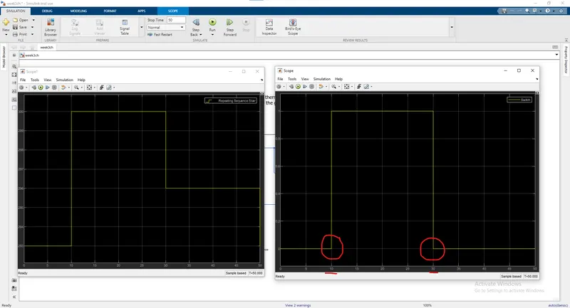
In the graph we can see that form 0-10 sec signal is “0” because in this time the temperature was 20℃ which is below 25℃ mean fan is switch off. After that from 10-30 sec signal is “1” because in this time the temperature was 27℃ which is above 25℃ means fan is switch on. At the end from 30-50 sec signal is “0” because in this time the temperature was 23℃ which is below 25℃ mean fans was switch off.