Week -2
Introduction to Physical Modeling using Simsacpe - Challenges - Week -2
Aim:-
1. Make a Simulink model of a Doorbell using a solenoid block with the following details:
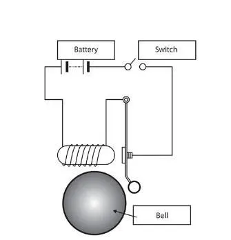
- In the above arrangement, when the switch is closed the electromagnet receives electrical power from the battery and pulls the metal arm to hit the bell producing sound.
- Create a situation where the switch is closed for 2 seconds and then released. Observe the physical movement of the plunger. Assume the remaining parameters.
2. Use a thermistor to sense the temperature of a heater & turn on or turn off the fan as per the below conditions:
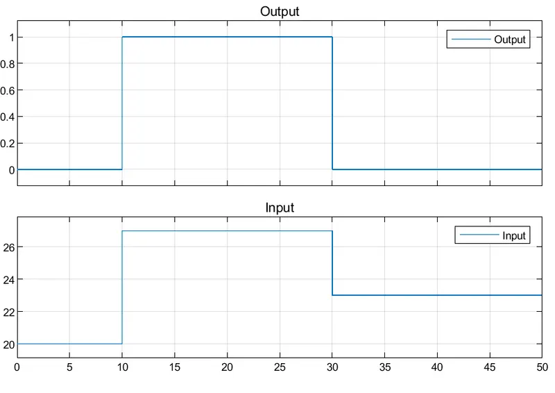
- Temperature source: 20 °C from 0 to 10 seconds, 27 °C from 10 to 30 seconds, 23 °C from 30 to 50 seconds
- Fan conditions: ON if the temperature is above 25 °C, OFF otherwise.
Theory:-
Solenoid - Doorbell - A chime doorbell uses a specialized sort of electromagnet called a solenoid. A solenoid is just an electromagnet where the coiled wire surrounds a metal piston/plunger. The piston contains magnetically conductive metal, so it can be moved backward or forward by the electromagnetic field.
The solenoid piston consists of an iron core mounted to a non-magnetic metal bar in many instances. When there is no power to the electromagnet, a spring pushes the piston to the left, and the iron core extends outside of the wire coil. When you turn the electromagnet on (by pressing the doorbell button), the iron core is drawn to the magnetic field, sliding into the coiled wire's center. As the iron core slides to the right, the end of the piston strikes the right-hand tone bar. The tone bar vibrates, producing a particular note. This is the "ding" sound.
As long as you hold the doorbell button, the current will flow through the electromagnet and the piston will remain in this position. But when you release the button, the current will stop flowing through the electromagnet and the magnetic field will collapse. The spring snaps the piston back to the left, where it hits the tone bar on the other side. The second tone bar produces the "dong" sound.
Blocks:-
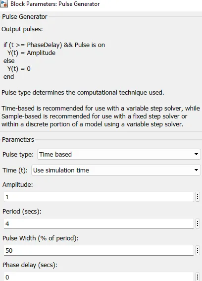
- Pulse Generator - The Pulse Generator block generates square wave pulses at regular intervals. The block waveform parameters, Amplitude, Pulse Width, Period, and Phase delay, determine the shape of the output waveform. The following diagram shows how each parameter affects the waveform.
- Simulink-PS Converter - The Simulink-PS Converter block converts the input Simulink signal into a physical signal.
- Switch - The Switch block models a switch controlled by an external physical signal. If the external physical signal PS is greater than the value specified in the Threshold parameter, then the switch is closed, otherwise, the switch is open.
- Battery - The Battery block represents a simple battery model.
- Electrical Reference - The Electrical Reference block represents an electrical ground. Electrical conserving ports of all the blocks that are directly connected to the ground must be connected to an Electrical Reference block. A model with electrical elements must contain at least one Electrical Reference block.
- Solenoid - The Solenoid block represents the electrical characteristics and generated force for the solenoid.
- Ideal Translational Motion Sensor - The Ideal Translational Motion Sensor block represents a device that converts an across variable measured between two mechanical translational nodes into a control signal proportional to velocity or position.
- Solver Configuration - Each physical network represented by a connected Simscape block diagram requires solver settings information for simulation. The Solver Configuration block specifies the solver parameters that your model needs before you can begin the simulation.
- Mechanical Translational Reference - The Mechanical Translational Reference block represents a reference point, or frame, for all mechanical translational ports. All translational ports that are rigidly clamped to the frame (ground) must be connected to a Mechanical Translational Reference block.
- PS-Simulink Converter - The PS-Simulink Converter block converts a physical signal into a Simulink output signal.
- Scope - Display signals generated during simulation
Thermistor - Heater - A thermistor is a type of resistor whose resistance is strongly dependent on temperature, more so than in standard resistors. The word thermistor is a portmanteau of thermal and resistor. Thermistors are divided based on their conduction model. Negative Temperature Coefficient (NTC) thermistors have less resistance at higher temperatures, while Positive Temperature Coefficient (PTC) thermistors have more resistance at higher temperatures. Hence, a PTC thermistor's resistance is directly proportional to temperature.
Thermistors are one of the most commonly used devices for the measurement of temperature. The thermistors are resistors whose resistance changes with the temperature.
An electric heater is an electrical device that converts an electric current into heat. The heating element inside every electric heater is an electrical resistor and works on the principle of Joule heating: an electric current passing through a resistor will convert that electrical energy into heat energy.
Main Blocks:-
- Signal Builder - To display, create, and edit interchangeable groups of signal sources and quickly switch the groups into and out of a model, use the signal builder block. You can define any piecewise linear signal shape (waveform).
- Thermistor - Thermistor block which shows the NTC thermistor relation between temperature and resistance.
- Control Temperature Source - The Controlled Temperature Source block represents an ideal source of thermal energy that is powerful enough to maintain specified temperature differences across the source regardless of the heat flow consumed by the system.
- Voltage Sensor - The Voltage Sensor block represents an ideal voltage sensor, that is, a device that converts voltage measured between two points of an electrical circuit into a physical signal proportional to the voltage.
- Resistor - The resistor which provides the opposing nature of current in a circuit.
- Thermal Reference - The Thermal Reference block represents a thermal reference point, that is, a point with an absolute zero temperature, concerning which all the temperatures in the system are determined.
- Switch - The Switch block passes through the first input or the third input signal based on the value of the second input. The first and third inputs are data inputs. The second input is a control input. Specify the condition under which the block passes the first input by using the Criteria for passing the first input and Threshold parameters.
Model:-
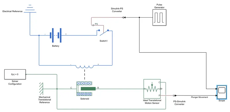
- The doorbell, a model is created. When the switch is closed the electromagnet receives electrical power from the battery and pulls the metal arm to hit the bell producing sound. Where the switch is closed for 2 seconds and then released. The physical movement of the plunger is observed.
- A solenoid is being connected to a battery and a switch where a pulse generator is connected to the switch through a Simulink-ps converter. Input signal as per the condition is given by a pulse generator where the changes have been made for the period and pulse width as 4 sec and 50% respectively to meet the condition for the switch to close and open.
- An ideal translational motion sensor is connected to read the position of the plunger and display the same as the output in the scope block. Scope block is used with the help of a ps-Simulink converter.
- The scope block is also connected to the pulse generator to read out the pulse movement and compare the same with the output signal for easy understanding. To run the simulation solver configuration block is connected to the model. A reference block is connected to electrical and mechanical blocks each.
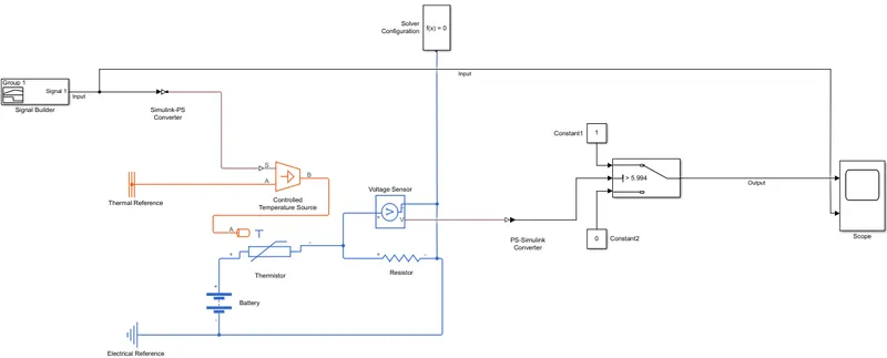
- The heater model is created using a thermistor to sense the temperature of the heater and to turn on the fan if the temperature is above 25°C otherwise off. A thermistor is connected with a controlled temperature source and a voltage sensor with a resistor circuit is then connected to the battery.
- A constant block of 25°C is used as input to the model to get its voltage of it through the voltage sensor, as the same voltage value is considered as the threshold value for the switch to follow the given condition.
- After getting the threshold value for the switch in place of a constant block as input a signal builder block is used to follow the condition for the model. In signal builder, a signal is created where the time axis(x-axis) has a maximum of 50 sec and the y-axis which is considered a temperature value has up to 28°C. As per the condition of the model from 0 to 10 sec, it is 20°C, from 10 to 30 sec it is 27°C and from 30 to 50 sec it is 23°C.

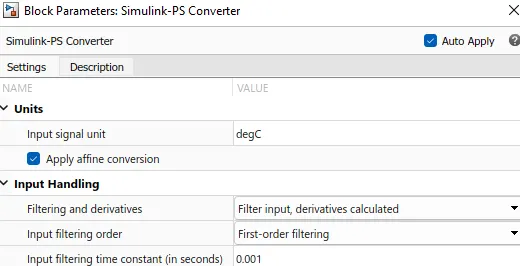
- Input for the temperature value is given in the block parameter of the Simulink-ps converter, under units as design and filtering and derivatives are selected as filter input derivatives calculated under input handling. Simulink-ps converter will throw an error stating "Not enough input derivatives were provided for one or more Simulink-ps converter". This is due to the solver type requiring fewer input derivates to solve the model. To resolve this, we need to select input handling>Filtering and Derivaties>Filter input, derivatives calculated from the Simulink-ps converter block parameters.
- After doing all the required changes a switch is connected to the circuit to work as per the model condition. The first and third data inputs are connected through a constant value of 1 and 0. The second input is a control input. Specify the condition under which the block passes the first input by using the Criteria for passing the first input and Threshold parameters.
- Scope block is connected to the switch output to display the on and off signal of the fan. The scope is also connected to the signal builder to visualize the input signal. A solver configuration to run the simulation and reference block for thermal and electrical used.
Result:-
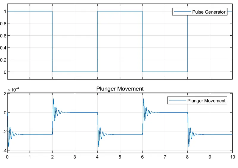
- In the below scope output the plunger movement can be seen and can be understood very easily when compared with the input signals through the pulse generator. The plunger is changing its position for 2 sec and returning back to its original position completing a cycle of 4 sec.
- From the below output it can be seen when the temperature is above 25 °C there is a movement of the signal and for the rest it is steady. Basically, there is the incline of the signal. That means the fan is on when the temperature is above 25°C otherwise off.