Week -2
1)
Objective: To model an Solenoid bell using simulink such that a situation is created where the switch is closed for 2 seconds and then released. Observe the physical movement of the plunger.
Simulink Model:
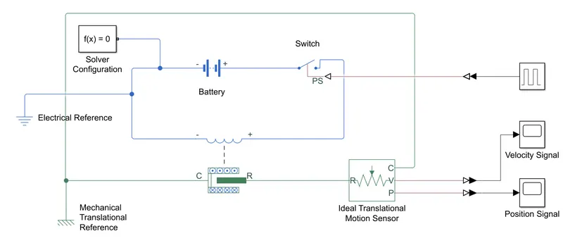
The above simulink model has the follwing blocks:
1) Solenoid
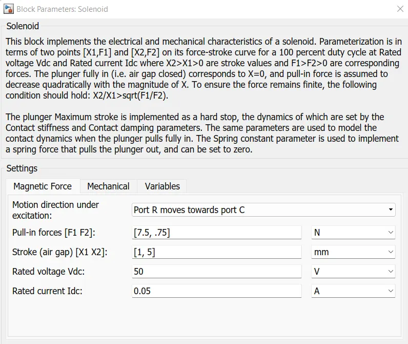
Here F1 and F2 are the forces corresponding to X1 and X2 and the rated voltage powers up the solenoid. The solenoid contains both electrical and mechanical connections depicted by blue and green. The green side depicts the plunger connceted to the solenoid which actuates when the solenoid gets excited.
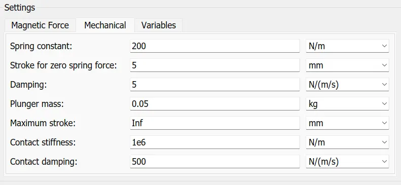
These are the plunger setteings given by spring constant, damping and plunger mass.
2. PWM Generator:
The PWM signals are provided by the generator to the switch such that our objective is met.
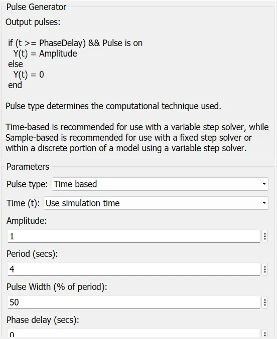
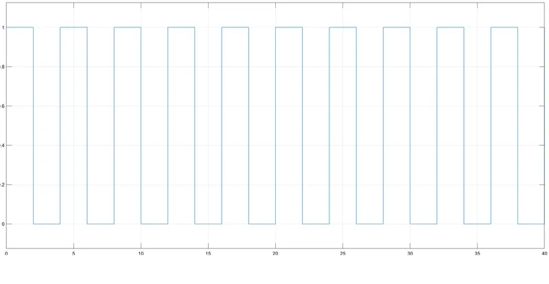
The block generates a pulse of unit amplitude for a period of 2 sec since pulse width is given as 50% of the total period which is 4 sec.
3. Switch
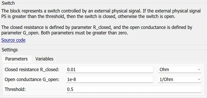
The physical signal from the PWM generator is connected to the Switch. And the switch remains closed if the physical signal is greater than the threshold value and opens otherwise.
The blue coloured electrical connection is controlled by the switch and the green coloured shows the mechanical connection or the door bell mechanism.
4. Battery
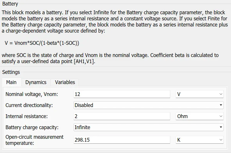
The battery used is 12V with internal resisitance as 2 ohms.
An electrical as well as mechanical translational references are provided for the electrical and mechanical connection. And the Solver settings are assigned by the Solver configuration for the simulation.
5. Mechanical System
The plunger connected to the solenoid moves when there is a current flowing through the solenoid. This causes the ringing action of the plunger, the plunger motion is measured by the Translational motion sensor.
Results:
1. Position Signal
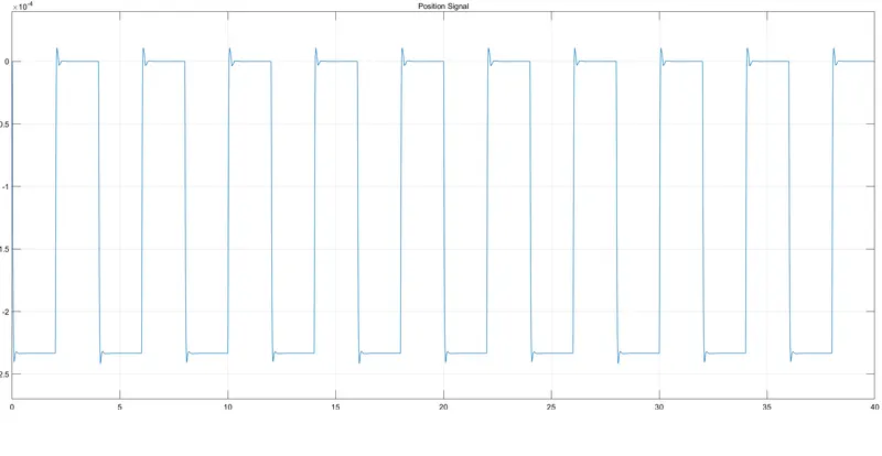
For the 1st two seconds when the switch is closed and the solenoid is energized the doorbell rings and at time=2 seconds, the circuit breaks and the spring of the plunger pull backs the plunger to the original position. Due to the stiffness of the spring the plunger oscillates for another few seconds due to the damping affect. By fine tuning the parameters that is spring constant and damping coefficient we can get a proper output.
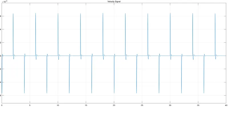
Velocity signal shows the velocity of the plunger during the ringing and releasing stage.
Hence, a simulink model of doorbell using solenoid block was simulated and the objective was met.
2)
A thermistor is a type of resistor whose electrical resistance varies with change in temperature.
Objective: Use a thermistor to sense the temperature of a heater & turn on or turn off the fan as per the below conditions:
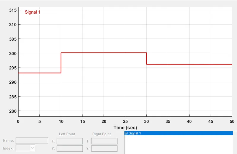
(Temperature source: 20 °C from 0 to 10 seconds, 27 °C from 10 to 30 seconds, 23 °C from 30 to 50 seconds)
(Fan conditions: ON if the temperature above 25 °C, OFF otherwise)
Simulink Model:
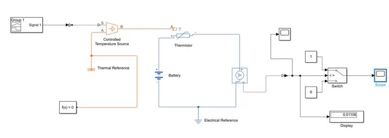
The above simulink model contains the following elements:
1. Controlled Temperature Source (Heater):
This block represents an ideal energy source in a thermal network that can maintain a controlled temperature difference regardless of the heat flow rate. The temperature difference is set by the physical signal port S. A positive temperature difference causes the temperature at port B to be greater than the temperature at port A.
2. Signal Builder:
To build a signal according to the temperature source condition (20 °C from 0 to 10 seconds, 27 °C from 10 to 30 seconds, 23 °C from 30 to 50 seconds) which is given as input to the Heater. The temperatures are converted from Celcius to Kelvin.
3. Thermistor:
This block represents an NTC thermistor using the B-parameter equation. The resistance at temperature T is given by R(T) = R0*exp(B*(1/T-1/T0)) where R0 is the Nominal resistance at the reference temperature T0, and B is the Characteristic temperature constant.
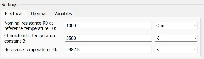
Electrical and thermal refererences are provided for the thermal and electrical connections and a solver configuration is also provided for the simulation.
4. Battery
Battery acts as the source of the Fan. The battery current flows through the loop and is resisted by the thermistor whose resistance varies with change in temperature. A 12V battery with 2 ohm internal resistance is used.
5. Current Sensor
The block represents an ideal current sensor, that is, a device that converts current measured in any electrical branch into a physical signal proportional to the current. Connections + and - are conserving electrical ports through which the sensor is inserted into the circuit. Connection I is a physical signal port that outputs current value.
Results:
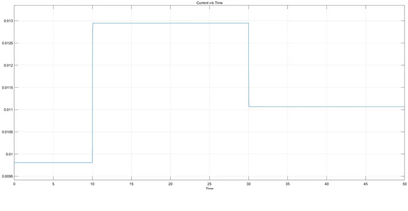
The graph shows the current through the loop. Here the thermistor is connected to the positive terminal of the battery and the negative side is connected to the current sensor. As we have considered an NTC thermistor, which means the resistance decreases with increase in temperature. Hence when the temperature of the heater increases from 10-30 seconds a considerable increase in current can be scene due to the decrease in resistance.
The Current sensor output is connected to a switch with a threshold value. The switch is provided with 2 inputs 0 and 1. Whenever the input current is greater than the threshold value of the switch it turns on or switch to 1.
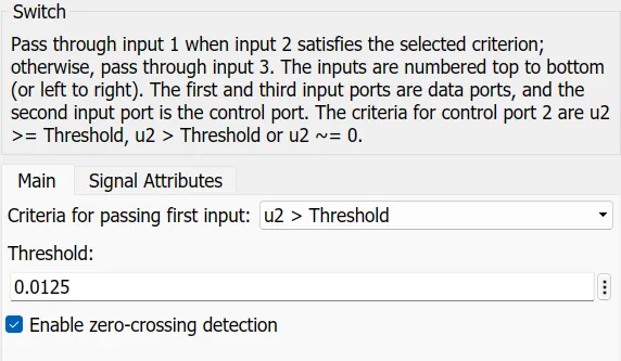
When it becomes less than the threshold value it turns to zero or the switch becomes off. With our objective where a fan is decided to be connected to the output of the switch. When the temperature is above 25 *C the fan is turned on which is depicted in the graph.
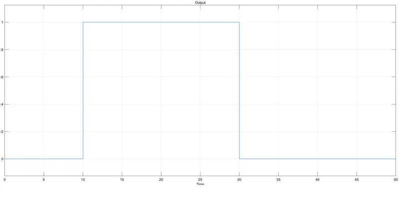
Hence our objective is satisfied, the fans turns on only when the heater temperature is 25 C.