Week -2
Q.1)Make a Simulink model of Doorbell using solenoid block with the following details:
In the above arrangement, when the switch is closed the electromagnet receives electrical power from the battery and pulls the metal arm to hit the bell producing sound.
Create a situation where the switch is closed for 2 seconds and then released. Observe the physical movement of the plunger.
ANS:
This is simulink model of doorbell using solenoid block,
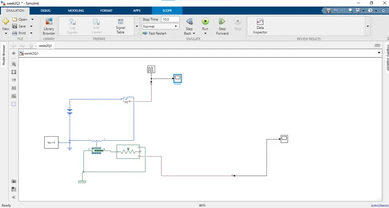
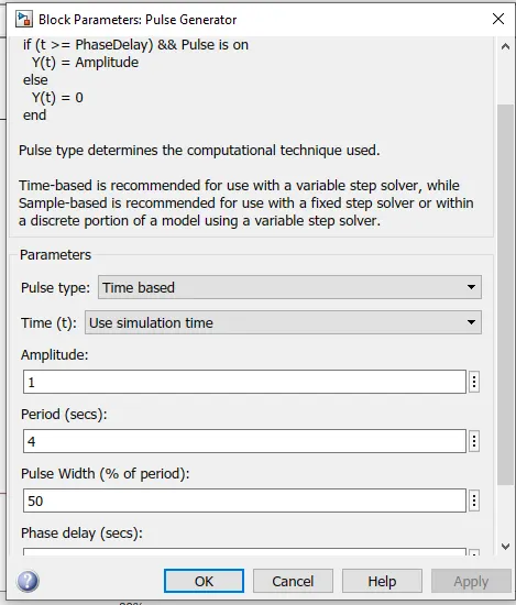
- This model required a pulse signal for ringing the bell for 2 sec. So I created pulse signal with the help of ‘Pulse Generator’ block and its parameters are Amplitude: 1, Period: 4sec., Pulse width: 50% of period and Phase delay: 2sec.
- After this create a block diagram as per the above figure with help of Battery, Electric switch, Solenoid and Ideal Translational Motion Sensor. Also connect Electrical and Mechanical Translational references with respective element blocks. Solver Configuration connects for solving equations of simscape physical networks.
- Also connect Scope, Display for results and PS-simulink converter for converting simscape physical model into the simulink model.
After all connections run the simulation with 10 sec stop time.
- I took parameter of pulse genarator as shown bellow
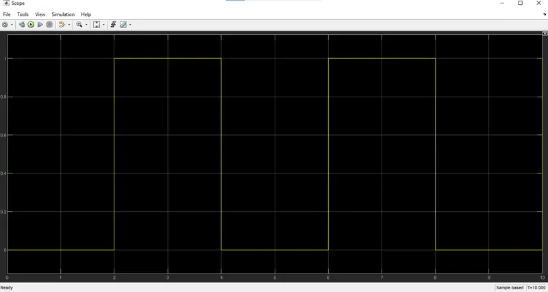
- This is input signal graph given to pulse generator recorded by scope.
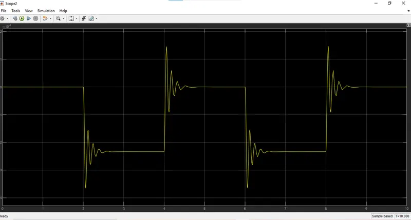
- After all connections run the simulation with 10 sec stop time.
- The below graph of output signals recorded by scope at output side
Result:
- Above shows the graph of Plunger Velocity, Plunger Position and Input of pulse generator.
- In the Pulse generator graph shows signal gives to the switch after every 2sec. And the switch is turn ON after the 2 sec switch get closed.
Also in plunger velocity and position fluctuate after every 2sec.
Q.2)Use a thermistor to sense the temperature of a heater & turn on or turn off the fan as per the below conditions:
Temperature source: 20 °C from 0 to 10 seconds, 27 °C from 10 to 30 seconds, 23 °C from 30 to 50 seconds
Fan conditions: ON if the temperature above 25 °C, OFF otherwise
ANS:
This is simulation model for thermistor by assuming given condition
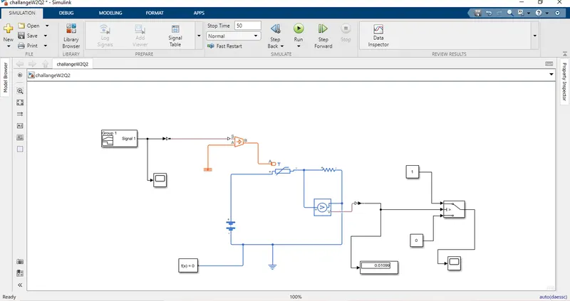
- This model is built for turn ON and OFF the fan as per the conditions.
- So for these conditions the signal is created by the signal builder.Signal Builder signal shows in below figure.
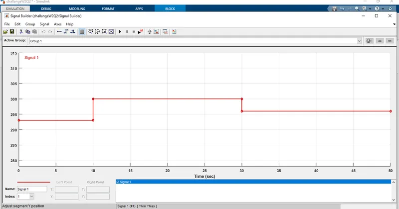
- Block diagram draw as per shown in above figure.
- Before the signal builder, signal gives to controlled temperature source block gives input the 298 kelvin i.e. 25°C through a constant block for calculating the threshold voltage of the resistor which is connected in the block diagram as a load.
- After calculating the threshold voltage gives the signal builder signal to the controlled temperature source for creating temperature as per our condition and passes to the NTC thermistor.
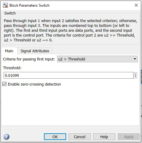
Also at the same time I used a switch for controlling the turn ON and OFF signal of the fan. For these switch gives a threshold value which I calculated earlier i.e. 0.03487 for 25°C. as shown in below fig
- Now run the simulation with 50sec stop time after completing the block diagram.
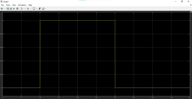
Result:
- In the result graph shows Signal Builder signal, Switch ON-OFF Signal and Voltage across the resistor.
- As per our condition switch signal ON when temperature goes above the 25°C, otherwise signal is OFF.