Week -2 : simulink model of doorbell and thermistor challenge
1. SIMULINK MODEL OF DOORBELL
AIM:-
Make a model of doorbell using solenoid block .
THEORY:-
Chime doorbell uses a specialized sort of electromagnet called a solenoid. A solenoid is just an electromagnet where the coiled wire surrounds a metal piston. The piston contains magnetically conductive metal, so it can be moved backward or forward by the electromagnetic field. In many instances, the solenoid piston consists of an iron core mounted to a non-magnetic metal bar. When there is no power to the electromagnet, a spring pushes the piston to the left, and the iron core extends outside of the wire coil. When you turn the electromagnet on (by pressing the doorbell button), the iron core is drawn to the magnetic field, so it slides into the center of the coiled wire. As the iron core slides to the right, the end of the piston strikes the right-hand tone bar. The tone bar vibrates, producing a particular note. This is the "ding" sound.
As long as you hold the doorbell button, current will flow through the electromagnet and the piston will remain in this position. But when you release the button, the current will stop flowing through the electromagnet and the magnetic field will collapse. The spring snaps the piston back to the left, where it hits the tone bar on the other side. The second tone bar produces the "dong" sound. You can make more elaborate tone sequences by adding more solenoids and tone bars.
SIMULINK MODEL :-
google drive link :
https://drive.google.com/file/d/1v0-Is4UBSEIfx-PBR9nZtaqdYynZtUHU/view?usp=sharing
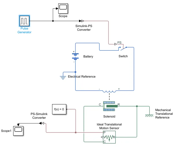
Simulink blocks used :
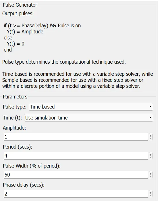
- Pulse generator : The Pulse Generator block generates square wave pulses at regular intervals. The block waveform parameters, Amplitude, Pulse Width, Period, and Phase delay, determine the shape of the output waveform. the input given to pulse generator is given below
-
Scope : Display signals generated during simulation . here scope next to pulse generator is used to view the signal generated by the pulse generator .
-
Simulink-PS-converter : Convert Simulink input signal into physical signal.
-
Switch : The Switch block models a switch controlled by an external physical signal. If the external physical signal PS is greater than the value specified in the Threshold parameter, then the switch is closed, otherwise the switch is open.
- Battery
- Electrical Reference : The Electrical Reference block represents an electrical ground. Electrical conserving ports of all the blocks that are directly connected to ground must be connected to an Electrical Reference block. A model with electrical elements must contain at least one Electrical Reference block. Battery is connected to electrical reference .
- Solenoid : The Solenoid block represents the electrical characteristics and generated force for the solenoid.
- Mechanical translational reference : The Mechanical Translational Reference block represents a reference point, or frame, for all mechanical translational ports. All translational ports that are rigidly clamped to the frame (ground) must be connected to a Mechanical Translational Reference block. solenoid is connected to mechanical transalational reference .
-
Ideal translational motion sensor : This block measures velocity or displacement in a mechanical translational network. The sensor is ideal since it does not account for inertia, friction, delays, energy consumption, and so on. this sensor is connected across solenoid . here we are measuring change in position of plunger by connecting 'p' port to another scope through a PS-Simulink convertor .
- Solver configuration : Each physical network represented by a connected Simscape™ block diagram requires solver settings information for simulation. The Solver Configuration block specifies the solver parameters that your model needs before you can begin simulation.
RESULTS :-
Pulse generator signals
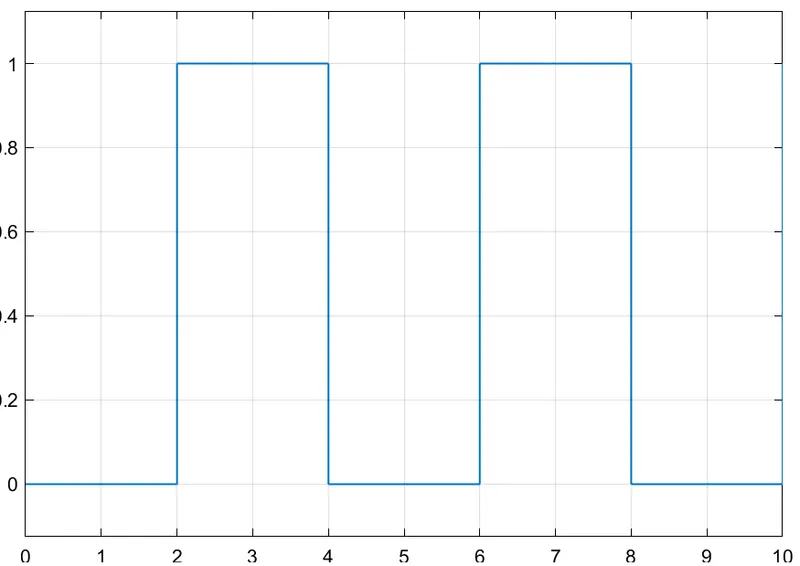
This plot shows how the pulse is generated in this simulink model . x-axis represents time and y-axis represents amplitude . when the amplitude is one the switch is closed for two seconds and when the amplitude is zero , the switch will be open .
Plunger position plot
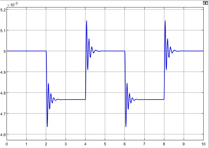
Here the x-axis represents the time and y-axis represents the position of plunger in mm . here the initial position of plunger is at 5 mm i.e. when the pulse generator at 0 amplitude . after 2 seconds when the amplitude of pulse generator is one , then there is change in position of plunger and it returns to initial position after two seconds . this cycle repeats till it reaches the simulation time .
CONCLUSION :-
We have successfully created the simulink model of doorbell with solenoid and observed the results .
2. THERMISTOR CHALLENGE
AIM:-
Use a thermistor to sense the temperature of a heater & turn on or turn off the fan
THEORY:-
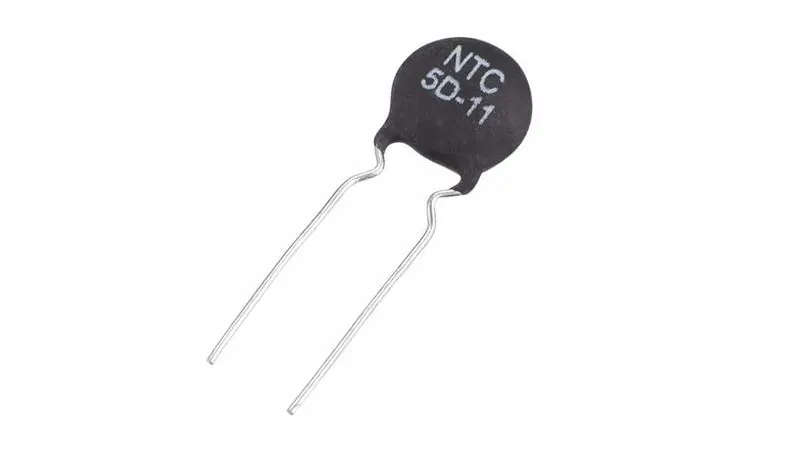
Thermistor: A thermistor is a semiconductor that has a resistance capacity more than a conducting material and less than insulating material. Its electrical resistance varies with the change in the temperature or thermally sensitive resistor. There are mainly two types of thermistors, namely the Negative Temperature Coefficient (NTC) and the Positive Temperature Coefficient (PTC).Thermistor’s relation with temperature also depends on the material in which it is made. A negative temperature coefficient (NTC) thermistor will decrease its resistance value when temperature increases whereas a Positive temperature coefficient will increase its resistance when temperature increases.
SIMULINK MODEL :-
google drive link :
https://drive.google.com/file/d/1rmX8rtz2mNnAlNGwaQYmEXe0FW6huoQo/view?usp=sharing
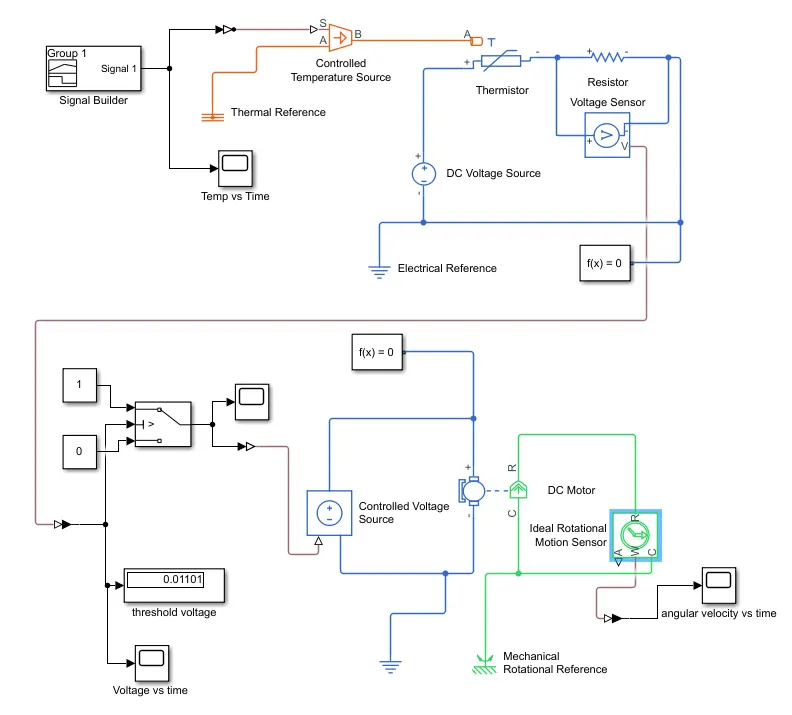
Simulink blocks used :-
1) Signal builder : The Signal Builder block allows you to create interchangeable groups of piecewise linear signal sources and use them in a model. You can quickly switch the signal groups into and out of a model to facilitate testing. In the Signal Builder window, create signals and define the output waveforms.
In this signal builder we are creating the following signals :
Temperature source: 20 °C from 0 to 10 seconds, 27 °C from 10 to 30 seconds, 23 °C from 30 to 50 seconds
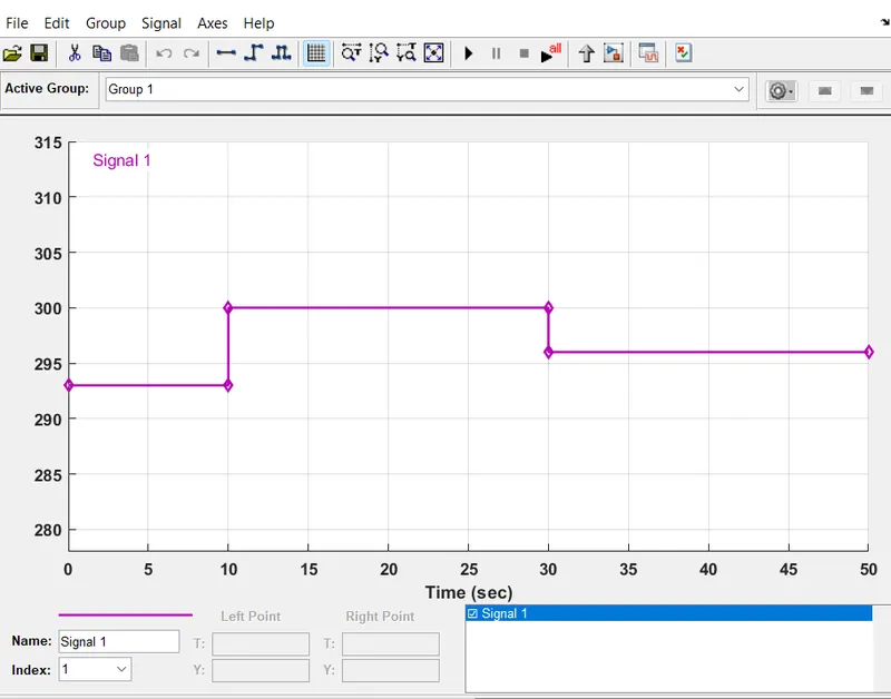
here the temperature is in kelvin .
2) Controlled temperature source : This block represents an ideal energy source in a thermal network that can maintain a controlled temperature difference regardless of the heat flow rate. signal builder block is connected to this block through a simulink-ps-converter .
3) Thermal reference : The Thermal Reference block represents a thermal reference point, that is, a point with an absolute zero temperature, with respect to which all the temperatures in the system are determined. thermal reference is connected to A port of controlled temperature source .
4) Simulink-PS-Converter: Converts the Simulink input signal to a Physical Signal. this is connected to signal builder which then connects to controlled temperature source .
5) Thermistor : The Thermistor block represents an NTC thermistor using the B-parameter equation . controlled temperature source is directly connected to thermistor . the positive terminal of thermistor is connected to positive terminal of DC Voltage source . and negative terminal of thermistor is connected to positive terminal of resistor .
6) Resistor : Linear resistor in electrical systems
7) Voltage sensor : The block represents an ideal voltage sensor, that is, a device that converts voltage measured between any electrical connections into a physical signal proportional to the voltage.Connections + and - are conserving electrical ports through which the sensor is connected to the circuit. Connection V is a physical signal port that outputs voltage value. voltage sensor is connected across resistor .
8) DC voltage source : The DC Voltage Source block maintains a time-invariant (constant) voltage across its output terminals, independent of the current through the source. voltage is 12V here.
9) Electrical reference : The Electrical Reference block represents an electrical ground. Electrical conserving ports of all the blocks that are directly connected to ground must be connected to an Electrical Reference block. A model with electrical elements must contain at least one Electrical Reference block.
10) Solver configuration : Each physical network represented by a connected Simscape™ block diagram requires solver settings information for simulation. The Solver Configuration block specifies the solver parameters that your model needs before you can begin simulation.
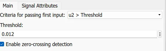
11) Switch :The Switch block passes through the first input or the third input signal based on the value of the second input. The first and third inputs are data input. The second input is a control input. using PS-Simulink converter we convert output voltage signal from voltage sensor to simulink output signal and fed it into switch . we change the threshold value of switch to 0.012 so that switch only works for the given condition . two constant 1 and 0 are connected to switch port 1 and 3 respectively .
12) constant : The Constant block generates a real or complex constant value signal. Use this block to provide a constant signal input. we use constant block 1 for ON condition and constant block 0 for OFF condition .
13) Controlled voltage source : The block represents an ideal voltage source that is powerful enough to maintain the specified voltage at its output regardless of the current passing through it. The output voltage is V = Vs, where Vs is the numerical value presented at the physical signal port. the signal from switch is converted to physical signal and given to controlled voltage source.
14) DC Motor : This block represents the electrical and torque characteristics of a DC motor. we are using this block for representing fan . this block is connected across controlled voltage source .
15) Ideal rotational motion sensor : This block measures angular velocity or angle in a mechanical rotational network. The sensor is ideal since it does not account for inertia, friction, delays, energy consumption, and so on. this block is connected parallel to dc motor to measure its properties .
16) Mechanical rotational reference : This block represents a mechanical rotational reference point, that is, a frame or a ground. Use it to connect mechanical rotational ports that are rigidly affixed to the frame (ground).
17) Scope : Display signals generated during simulation . we have used 4 scopes in this simulink model .
18) Display : displays the input values .
19) PS-Simulink-Converter : Converts the input Physical Signal to a Simulink output signal.
RESULTS :-
Temp vs time plot of signal builder:
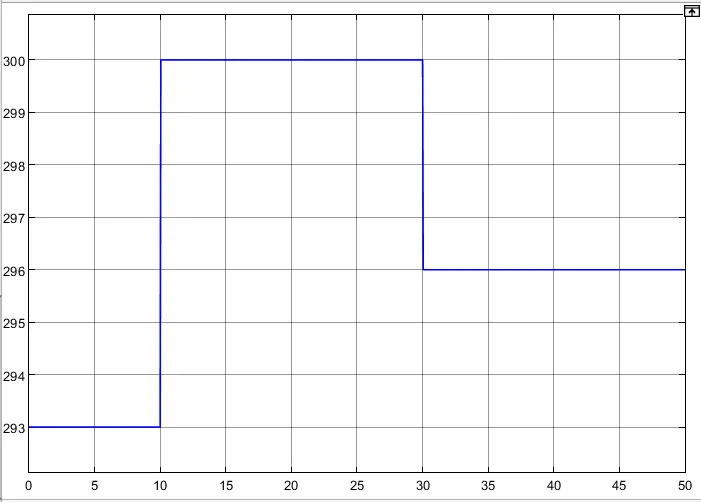
here x-axis represents time in seconds and y- axis represents temperature in kelvin
switch on / off plot :
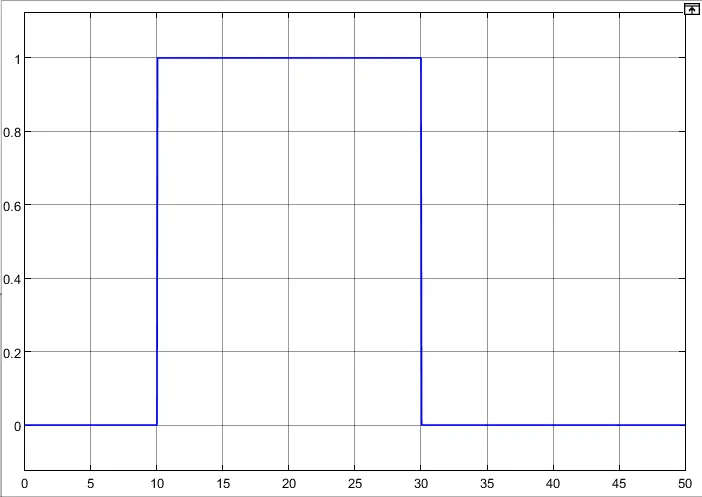
here x-axis represents time in seconds and y- axis represents amplitude . when the amplitude is 1 , then the switch is ON and when the amplitude is 0 , then the switch is OFF . from the plot it is clear that the switch only be in ON position between 10 and 30 seconds when the temperature is above 25 degree celcius .
voltage vs time plot :
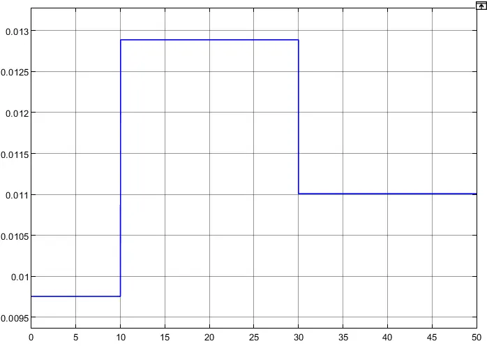
here x-axis represents time in seconds and y- axis represents voltage . the reason for threshold value 0.012V in switch is because when we observe plot above we can see that in order to satisfy our on/off condition the value should be greater than 0.11
angular velocity vs time plot of dc motor:
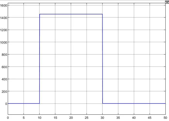
here x-axis represents time in seconds and y- axis represents angular velocity of dc motor .
CONCLUSION:-
We have successfully made simulink model for switching the fan on/off for given condition using thermistor by sensing the temperature of heater .
REFERENCE :-
Google
Wikipedia
Simulink documentation