Week -2
AIM:
1. To make a Simulink model of door bell using solenoid block.
2. To make a Simulink model using a thermistor to sense the temperature of a heater and turn on or off the fan.
Door-bell model:
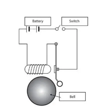
Working
The door-bell is the device having electrical and mechanical component that works when pressed.When the switch is pressed the circuit flow is complete,which passes the current to flow throught the circuit.
SIMULINK MODEL:
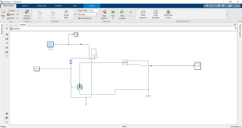
1.DOOR BELL USING SOLENOID:
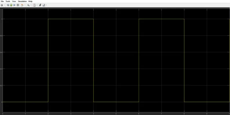
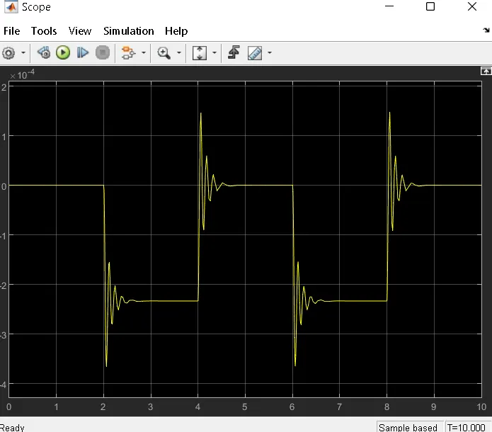
Output:
Important blocks used in this model and their uses:
Inputs:
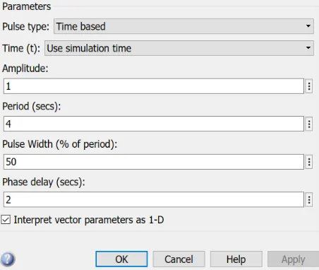
Pulse generator
Pulse type determines the computational technique used.Time-based is recommended for use with a variable
step solver, while Sample-based is recommended for use with a fixed step solver or within a discrete portion of a
model using a variable step solver.
Switch:
The Switch block models a switch controlled by an external physical signal. If the external physical signal PS is
greater than the value specified in the Threshold parameter, then the switch is closed, otherwise the switch is open.
Battery:
The Battery block represents a simple battery model. The block has four modeling variants, accessible by right-
clicking the block in your block diagram and then selecting the appropriate option from the context menu,
under Simscape > Block choices:
Solenoid:
The plunger Maximum stroke is implemented as a hard stop, the dynamics of which are set by the Contact
stiffness and Contact damping parameters. The same parameters are used to model the contact dynamics when
the plunger pulls fully in. The Spring constant parameter is used to implement a spring force that pulls the plunger
out, and can be set to zero.
Model Explanation:
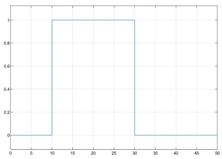
- In this model first i have been taken the switch which is controlled by pulse generator block to given the inputs
of 4 i.e when 2 seconds for the switch is open and another 2 seconds for the switch is closed so, i can create a
situation when the switch is closed for 2 seconds and opn for two seconds.Then i take the battery block to given
the current supply for that. - When the battery and switch i have been connected into solenoid block which is available in simulink physical
system. - Then i'll use the mechanical translational sensor to sense the movement of plunger on the solenoid valve.The
scope is connected to the ideal translational sensor which shows the graphical reference of movement of
plunger. - In this case i'll use the mechanical referece and solver configration for simulation.
2.SIMULINK MODEL FOR USING THERMISTOR:
Automatic Temperature Control, as its name implies, is an automatic climate control system, which automatically
controls interior temperature based on the driver's demands and temperature information from various sources.
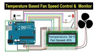
ATC does this through direct interaction with the vehicle's A/C and heating systems.so, in this case | have been given a
input signal from the thermister to the D.C motor.once the temperature is achieved the thermister sence the
temperature and given the signal to the D.C motor then the motor starts rotates to control the temperature.
Block model
Explanation
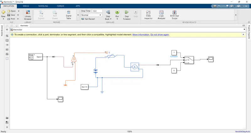
In this model i have been created the simulink blocks to sence the temperature of heater by the thermister to turn
on and turn off the fan whenever required-First i will take the thermister and connect it to the controlled temp
source.when the controlled temp sourse requires the input of temperature difference,over here we have 3 different
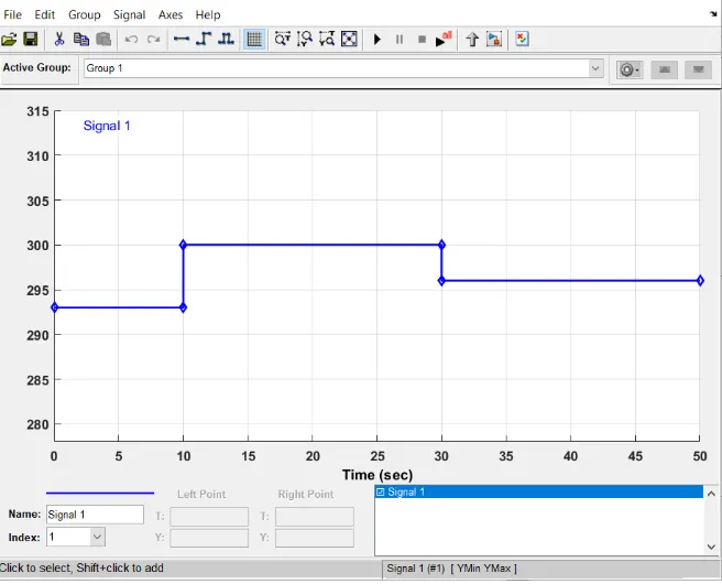
temperature sourse so thats why im taking the controlled temp sourse and connet it to the signal builder, With the
help of this Signal builder block to set the 3 difference of temp W.R.T time and given the input to controlled temp
source.After that i can connect the battery and resistor it would supply the required current to the D.C motor when
ever they required.in this case i can use the voltage sensor block to supply the inputs value three temp to the switch
which is gained from the thermister.When the switch having three inputs input 1&3 are data ports and input 2 are
control port which is known as u2,our main aim of this challange is to turn ON the fan at 25 degree celcius .ll given
the inputs of the switch is u2 > threshold force ie the value given by the voltage sensor is greater then the u2 value
means conect to the I st data port until connect the 2nd data port.Now the switch is closed or opened with respect to
comparision of threshold and u2 value.when the switch is closed its spplies the power to the controlled voltage
source block it will try to rotate the D.C motor.
Important blocks used in this model:
signal builder- This block is used to given the varaion of inputs as per the project requirments with respect to x
&y co-ordinates.
controlled temp source- This block is an physical system block in a thermal network it will maintain the temp
difference of the heat flow
Thermiater- The Thermistor block represents an NTC thermistor which is used to sense the temp from the
thermal source.
voltage sensor- The block represents an ideal voltage sensor, that is, a device that converts voltage measured
between any electrical connections into a physical signal proportional to the voltage.
Input switch - This block contains 3 inputs when Pass through input 1 when input 2 satisfies the selected
criterion; otherwise, pass through input 3. The inputs are numbered top to bottom (or left to right). The first and
third input ports are data ports, and the second input port is the control port. The criteria for control port 2 are
u2 >= Threshold, u2 > Threshold or u2~= 0.
Controlled voltage source - The block represents an ideal voltage source that is powerful enough to maintain
the specified voltage at its output regardless of the current passing through it. The output voltage is V = Vs,
where Vs is the numerical value presented at the physical signal port.
D.C Motor - This block represents the electrical and torque characteristics of a DC motor.
Ideal rotational motion sensor - In this case the block measures the angular velocity or angle in a mechanical
rotational network of the D.C motor.
Conclusion:
1. Thus, both the door bell using solenoid and Using a thermistor to sense the temperature of a heater & turn on or turn off the fan as per the below conditions objectives were achieved successfully.
2. Similar types of models can be used for simulating other physical devices using Simulink.