Week -2
QUESTION 1 :
AIM :
Make a Simulink model of Doorbell using solenoid block.
OBJECTIVE :
Create a situation where the switch is closed for 2 seconds and then released. Observe the physical movement of the plunger.
THEORY:
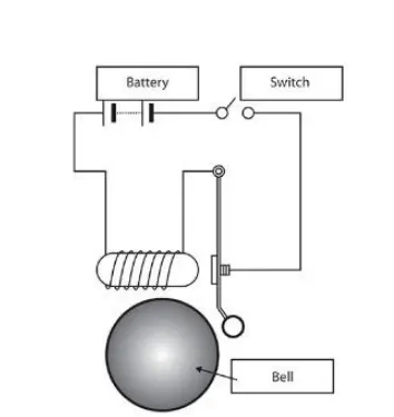
Basic components to generate a doorbell circuit are,
- Battery
- Switch
- Solenoid
- Bell with plunger ( we use sensor to detect the motion)
Solenoid
A solenoid is a device comprised of a coil of wire, the housing and a moveable plunger (armature). When an electrical current is introduced, a magnetic field forms around the coil which draws the plunger in. More simply, a solenoid converts electrical energy into mechanical work.
- The coil is made of many turns of tightly wound copper wire. When an electrical current flows through this wire, a strong magnetic field/flux is created.
- The housing, usually made of iron or steel, surrounds the coil concentrating the magnetic field generated by the coil.
- The plunger is attracted to the stop through the concentration of the magnetic field providing the mechanical force to do work.
SIMULINK MODEL
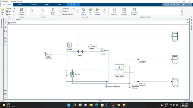
Simulink model link
click here to see the Doorbell Simulink model
EXPLANATION :
- As we know from the above given diagram of doorbell. We need basic components such as solenoid, battery and switch.
- The components are taken from the library browser in the respective groups.
- The solenoid is taken from electrical/ electromechanical/ mechatronics actuators.
- The battery and switch are taken from library browser
- The switch block, battery and solenoid electrical part are connected in series.
- An Electrical reference is use to ground it.
- The switch is connected to the pulse generator to give binary values to the switch to perform ON and OFF condition automatically.
- But the pulse generator and switch are not connected directly because the pulse generator is Simulink block and switch is Simscape block.
- So, to connect these two we have to use the Simulink – PS convertor block.
- To detect the translation motion of the plunger in the solenoid. We have to use a sensor to measure it.
- An Ideal translation motion sensor block is inserted from the library browser.
- The solenoid mechanical part and ideal translational motion sensor are connected in series with a mechanical reference.
- From the port V in Ideal translation motion sensor block the Velocity of the plunger used in the doorbell can be determined.
- Same From port P the position of the plungers can be determined.
Pulse generator dialog box image
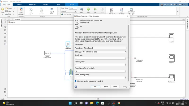
In the pulse generator the following to enter,
Pulse type: time base
Amplitude: 4
Period in sec: 4
Pulse width in % of period: 50
Phase delay in sec: 2
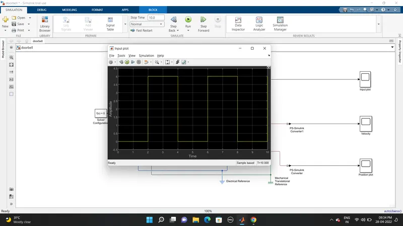
- The generated pulse can see using a scope in the connection.
- The pulse changes the phase in every 2 seconds. This helps to change the switch condition ON / OFF
- A solver configuration is connected in the electrical circuit. The Solver Configuration block specifies the solver parameters that your model needs before you can begin simulation.
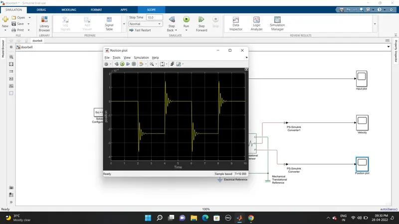
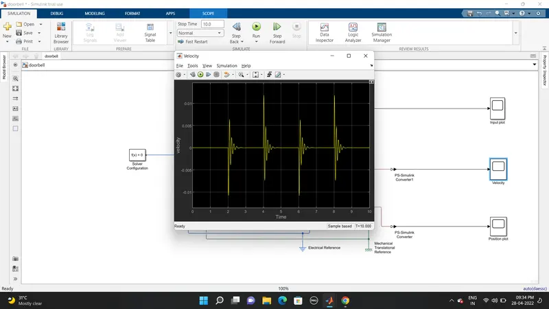
- We can observe that whenever there is a change in position of plunger, there are some waves forms at the start of changes in position. This is due to recoil of spring, each time when the plunger is moving. So, to reduce this, in the solenoid block we can increase the damping coefficient and reduce the spring constant. This will reduce the wave that are formed.
INPUT PULSE PLOT:
OUTPUT PLOT :
Position plot:
Velocity Plot:
QUESTION 2 :
AIM:
Use a thermistor to sense the temperature of a heater & turn on or turn off the fan as per the below conditions
OBJECTIVE:
Temperature source: 20 °C from 0 to 10 seconds, 27 °C from 10 to 30 seconds, 23 °C from 30 to 50 seconds
Fan conditions: ON if the temperature above 25 °C, OFF otherwise
THEORY:
Basic components to generate a thermistor sensing circuit are,
- Temperature source
- Thermistor
- Battery
- Resistor
- Voltage sensor
- Switch
- Motor
Thermistor
A thermistor is a resistance thermometer, or a resistor whose resistance is dependent on temperature. The term is a combination of “thermal” and “resistor”. It is made of metallic oxides, pressed into a bead, disk, or cylindrical shape and then encapsulated with an impermeable material such as epoxy or glass.
There are two types of thermistors: Negative Temperature Coefficient (NTC) and Positive Temperature Coefficient (PTC). With an NTC thermistor, when the temperature increases, resistance decreases. Conversely, when temperature decreases, resistance increases. This type of thermistor is used the most.
A PTC thermistor works a little differently. When temperature increases, the resistance increases, and when temperature decreases, resistance decreases. This type of thermistor is generally used as a fuse.
Typically, a thermistor achieves high precision within a limited temperature range of about 50ºC around the target temperature. This range is dependent on the base resistance.
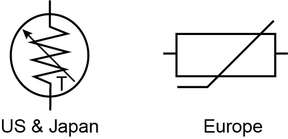
The thermistor symbols are:
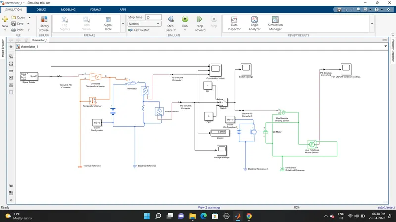
SIMULINK MODEL
Simulink model link
Click here to see the Temperature controlled Thermistor model
EXPLANATION :
In the above block diagram.
First part (create the varying temperature source according to the input.)
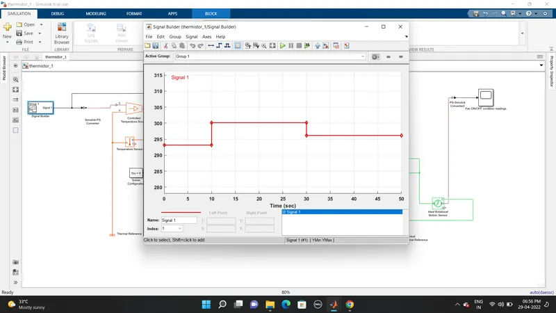
- The input temperature is given by signal builder in kelvin. The given three temperature are
20 ° C = 293.15 K (0 to 10 sec)
27 ° C = 300.15 K (10 to 30 sec)
23 ° C = 2296.15 K (30 to 50 sec)
- It's now connected to the controlled temperature source block through Simulink – PS convertor
- The controlled temperature source is connected to the temperature sensor and thermal reference.
Second Part (Temperature sensing)
- It now connected to a thermistor to give resistance according to the input temperature with respect to time.
- A voltage sensor is connected parallel to the resistor which is series with the thermistor to determine the voltage drop given by thermistor. The resistor will exhibit same resistance as thermistor.
- A solver configuration and electrical reference is connected to the circuit.
- A current sensor block is also connected in series with components to determine the current.
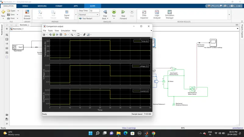
- A scope is use to visualize the voltage and current, to the corresponding input signals changes in thermistor.
Third Part (Switch)
- The output from the voltage sensor is connected to switch to satisfy the given condition.
- PS- Simulink convertor is use to connect the voltage sensor signal and switch.
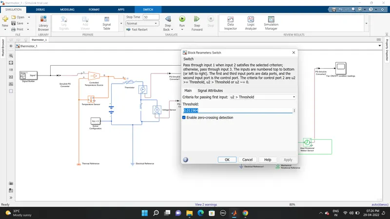
- Voltage threshold value of 25 ° C is found and given as an input to the switch as condition as 0.011964 value
- If the temperature exceeds the threshold value it is in ON condition. And give output. IF it is below threshold, it gives zero.
Fourth Part (create a motion using a DC motor)
- The pulse generated by the switch is given as input to the ideal angular velocity source through Simulink –PS convertor which is connected to a DC motor with a battery.
- To determine the motion of fan, an Ideal rotational motion sensor is connected.
- The electrical reference and solver configuration is connected to the electrical circuit.
- The mechanical rotational reference is connected to the DC motor.
- The motion of fan is plotted using a scope block through PS-Simulink convertor.
Signal Builder (Input signal)
Switch Threshold parameter
Comparison of temperature, voltage and resistance.
The voltage and current are directly proportional. So, whenever voltage increases current also increases.
Switch Condition:
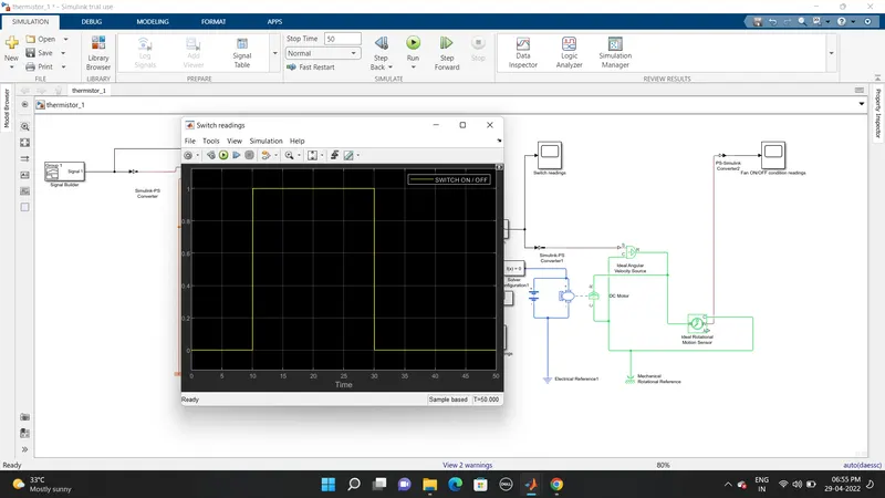
In the above plot the temperature source at 20°C from 0 to 10 seconds switch in OFF condition, at 27°C from 10 to 30 seconds switch in ON condition, at 23°C from 30 to 50 seconds switch in OFF condition.
Fan Condition:
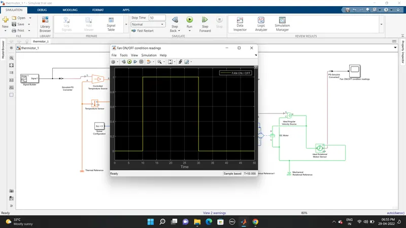
In the above plot the temperature source at 20°C from 0 to 10 seconds fan in OFF condition, at 27°C from 10 to 30 seconds fan in ON condition, at 23°C from 30 to 50 seconds fan in OFF condition.
Reference: