Week -2
Aim:-
1. To make a Simulink model of Doorbell using solenoid block.
2.To make a Simulink model using a thermistor to sense the temperature of a heater and turn on or turn off the fan.
PART-1 :- To make a Simulink model of Doorbell using solenoid block.
Objectives:-
1. For the model of Doorbell using solenoid block we have to create a situation where the switch is closed for 2 seconds and then released. And observe the position of the plunger.
Theory:-
Solenoid:
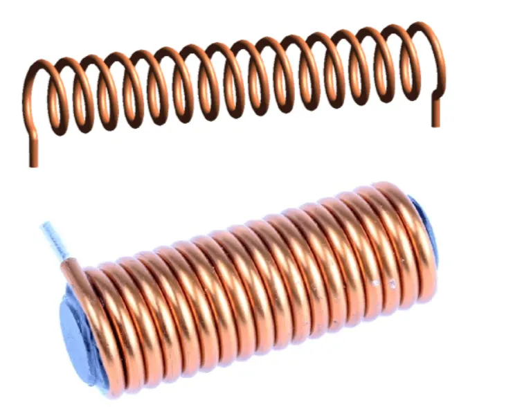
A solenoid is a long piece of wire which is wound in the shape of a coil. When the electric current passes through the coil it creates a relatively uniform magnetic field inside the coil.The solenoid can create a magnetic field from electric current and this magnetic field can be used to generate a linear motion with the help of a metal core. This simple device can be used as an electromagnet, as an inductor or as a miniature wireless receiving antenna in a circuit.
The solenoid simply works on the principle of “electromagnetism”. When the current flow through the coil magnetic field is generated in it, if you place a metal core inside the coil the magnetic lines of flux is concentrated on the core which increases the induction of the coil as compared to the air core.
The magnetic strength of the solenoid can be increased by increasing the density of the turns or by increasing the current flow in the coil.
Like all other magnets the activated solenoid has both Positive and Negative poles, through which an object can be attracted or repelled.
Simulink Model :-
DOOR BELL:-
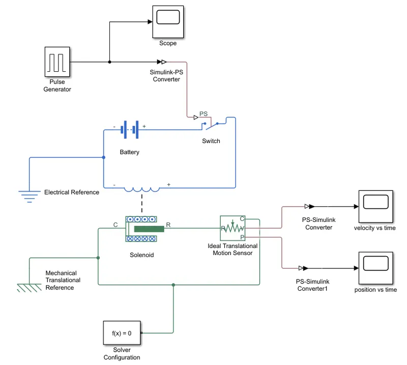
Blocks Used :-
1. Pulse generator
2. Switch
3. Voltage source
4. solenoid
5. Mechanical reference
6. Ideal translation motion sensor
7. Electrical reference
8. Solver configuration
9. Scope
Explanation:-
1. For create doorbell model in simulink we need above blocks.
2. Now first a 'solenoid block' is taken to represent a solenoid in the model , then we take a 'Battery block' fron the library browser.
3. Then this solenoid and battery block is connected through the positive and negative terminals.
4. A 'switch block' is used between the 'Solenoid block' and 'Battery block'.
5. Now for the switch to operate we must provide a physical signal through 'PS' port in the 'Switch Block'. The provided physical signal must be greater than the threshold of the switch, for the switch to be closed or else it will be opened.
6. Now this whole battery, switch and solenoid path is connected to 'Electrical Reference block' which represents the earthing of the circuit. The 'Electrical Reference block' should be connected with the negative terminal of the 'Battery Block'.
7. Then in the 'Solenoid Block', 'R' and 'C' are two variables which represent the plunger and fixed point respectively.
8. Now this 'R' is connected to an 'R' of the 'Ideal Translational Motion sensor block' which senses the position of the plunger in the 'solenoid block' and give the output.
9. Now the 'Ideal Translational Motion sensor block' the outputs are given as V and P which represent the velocity and the position of plunger. Since ,we need to observe velocity and the posotion of plunger, we need the results from 'P' output and 'V' output.
10. Now the 'C' in the 'Ideal Translational Motion Sensor Block' represent the mechanical translation conversion port which means that the mechanical process starts from 'R' and ends at 'C' and it again starts from 'R' and the cycle goes on.
11. And 'C' of 'Ideal Translational Motion Sensor Block' is connected to 'Mechanical Translational Motion Block' which represent a fixed point where it is rigidly clamped in real time.
12. Similarly, 'C' of the solenoid block is also connected to 'Mechanical Translational Motion Block' which represent as a fixed point for the solenoid.
13. In between port 'P' of 'Ideal Translational Motion Sensor Block' and 'scope block' and port 'V' of 'Ideal Translational Motion Sensor Block' and 'scope block' we connected ' 'PS-Simulink converter block', to convert physical value to simulink values for generating graph.
14. Now to provide a physical signal for operating the switch we used the 'pulse generator block' which generate a continuous square pulse.
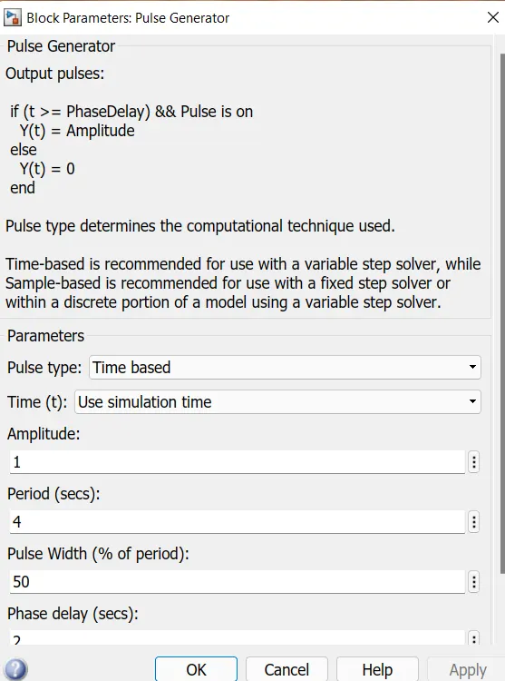
15. From the above figure we can observe that we have given period value as '4' , pulse width as '50', phase delay as '2', and amplitude by default is '1'. This means that initially the pulse will be zero and at 2 sec the pulse width will half of the periods, so for the next 2 sec the pulse will be at amplitude '1' only then it will again come down to zero at 4th sec and then it will at zero for next 2 sec thus completing the periods of 4 seconds.
16. From starting to ending of the pulse will take 4 sec of time period in which only for 2 sec the amplitude will be one and for rest of time it will be zero. So after these 4 sec period again the pulse will be generated and thus cycle continues.
17. To this 'Pulse generator block' a 'Scope block' is connected to see how the pulse is generated.
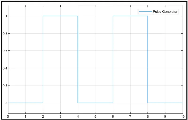
18. As mentioned before, the pulse has started after 2 seconds, then for next two seconds it has amplitude of 1 and then next 2 sec the pulse is again zero. The pulse is starting from 2 sec and ending at 6 sec which nothing but a time period of 2 seconds.
19. Thus, this represents that when amplitude is one, the switch will be closed and when it is zero the switch will open. Since our objective is only to see the change in position of plunger when switch is closed for 2 sec so that we have the amplitude as 1 for 2 seconds in the pulse generator by making the pulse width half of the period in the inputs for 'Pulse generator block'.
20.Since the pulse that is coming from 'pulse generator block' is a simulink value so to convert this into physical value we have used 'simulink-PS converter block'.
21. 'Solver configuration block' is connected to 'solenoid block' and 'ideal translational motion sensor block' path which generate equations and solve the whole model internally to give the results.
Results:-
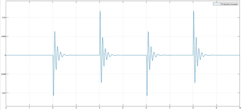
velocity vs time graph-
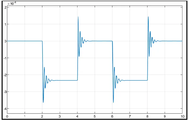
Position vs time graph
PART-2:- To make a Simulink model using a thermistor to sense the temperature of a heater and turn on or turn off the fan.
Objectives:-
1. For the model to use a thermistor to sense the temperature of heater and turn on and off the fan as per the below conditions;
1. Temperature source:
1. 20°C from 0 to 10 seconds.
2. 27°C from 10 seconds to 30 seconds.
3. 23°C from 30 seconds to 50 seconds.
2. Fan conditions:
1. ON if the temperature is above 25°C, otherwise OFF.
Theory:-
Thermister-
A thermistor is a type of rasistor whose resistance changes with the change in temperature. It is a passive component that does not require an extra power source to operate. They are inexpensive and accurate in measuring temperature. But they do not operate well in extreme conditions such as very high or very low temperatures.
Thermistors are a type of semiconductor, meaning they have greater resistance than conducting materials, but lower resistance than insulating materials.
A thermistor is made of semiconductor material whose resistance greatly depends on the surrounding temperature. They significantly vary with the temperature. Depending on the material used, the resistance may either increase or decrease with an increase in temperature called the PTC and NTC thermistor.
Types of Thermistor
There are two types of thermistors
- PTC (Positive Temperature Coefficient) Thermistor - with increase in temperature resistance also increase.
- NTC (Negative Temperature Coefficient) Thermistor -with increase in temperature resistance decrease.
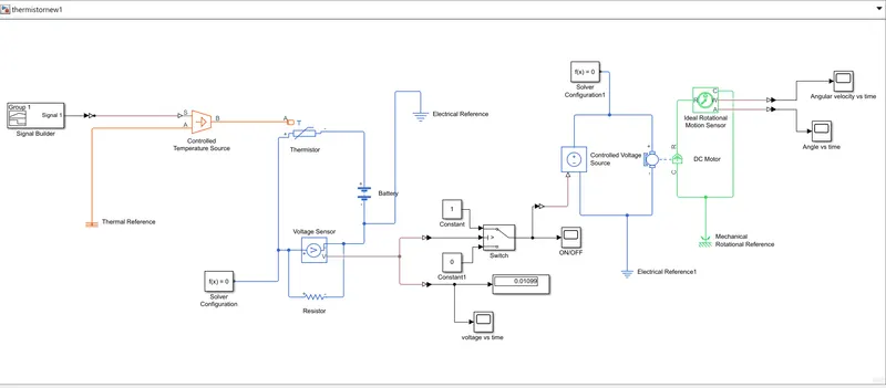
Simulink model:-
Blocks Used:-
1. Signal builder
2. Scope
3. Controlled Temperature Source
4. Thermister
5. Resistor
6. Voltage source
7. Electrical references
8. Voltage sensor
9. Simulink-PS convertor
10. PS-Simulink convertor
11. Display
12. Switch
13. Constants
14. DC Motor
15. Ideal Rotational Motion sensor
16. Mechanical Rotational reference
17. Solver configuration
Explanation:-
1. To create a simulink model Using thermistor to sense the temperature of a heater & turn on or turn off the fan as per the below conditions we need thermistor ,battery ,resistor ,voltmeter, alogical switch are basic component of the circuit we need in the simulink model.
2. First we use a 'Thermister block' and 'Battery block' and connect them in which positive port of battery is connected to negative port of thermistor.
3. Now take 'Resistor block' from library browser and it's positive port is connected to positive port of the 'Thermistor block'. The negative port of the 'Resistor block' is connected to the negative port of 'Battery block'. Now an 'Electrical reference block' is connected near the negative terminal of 'battery block'.
4. 'Solver configuration block' is connected to the circuit near positive port of 'voltage sensor block'.
5. The thermistor is connected to an 'Controlled temperature sourse block' for sensing the temperature. and 'Controlled temperature sourse block' is connected to 'Signal builder block' through 'Simulink-PS converter block'.'Simulink-ps convertor block' is used to convert signals to physical values. Thermal reference block' is connected to the 'A' port of 'Controlled temperature sourse block'
6. In 'signal builder block' we set the signal according to our requirement.
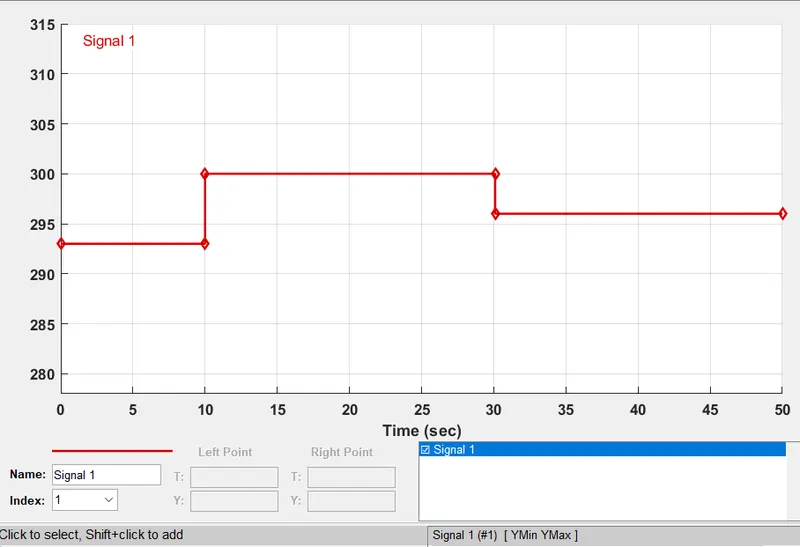
7. Above figure shows how the signal are set in the 'Signal builder block' . As this dialogue box opens, first we have to click on the "signal" at the top and then select "new" then select "custom" option. Now ot will ask to give the values of y-axis and x-axis. since we know that at which time, we need which temperature as mentioned in the starting , we can give those values in an array in this box and then the above figure signals are generated.
8. For measure the voltage difference we use 'Voltage sensor block' which is connected parallel to the 'resistor block'.
9. Since the fan is supposed to turn on when the temperature is 298K or above , the value of voltage corresponding to temperature 298K is given to the switch as threshold value.
10. The switch turns on when the voltage reaches it is threshold value.
11. This turn on the DC motor (Fan).
12. The output of a switch is connected to 'controlled voltage source block' through 'simulink to PS convertor block'. And 'Electrical reference block' is connected to this ckt near 'controlled voltage source block'.
12. A DC motor is used which has it's one end connected to 'controlled voltage source block' and other and to a 'Ideal Rotational motion sensor block'. a 'solver configuration block' is connected to motor circuit to solve the model. And 'Mechanical rotational reference block' is connected to motor ckt for connect rotational parts that are rigidly affixied to the frame.
13. The output from 'Ideal Rotational motion sensor block' is connected to scope through 'PS-Simulink block' to get both angular displacement and velocity of the motor.
Results:-
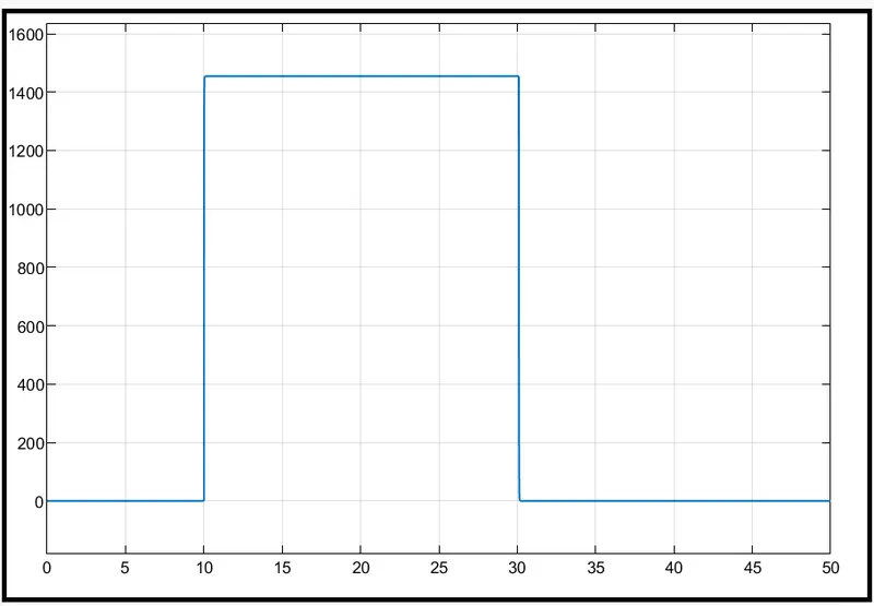
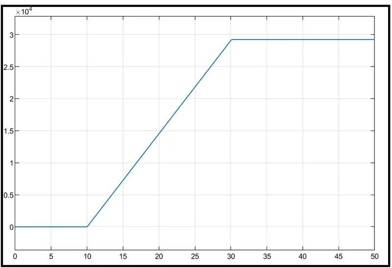
Angular velocity of motor vs time graph-
Angle vs time graph-
Conclusion:-
PART-1
The doorbell model was created and executed. we observed that there was a change in position of plunger when electricity was passed into the solenoid.
PART-2
The thermister model was created and executed.
As we can see the fan (DC Motor) is turned on for 20 seconds between t = 10-30sec when the temperature is more than 25°C .