Week -2
#PART 1 :
Aim : To Make a Simulink model of Doorbell using solenoid block
Objective : Make a simulink model of doorbell by using solenoid block
Theory :
- A doorbell is a device having mechanical and electrical components which produce sound on pressing the button
- When switch is getting closed the circuit get completed and current is passed
- Solenoid generates the electromagnetic wave and this allows the plunger to move
- because of this various conditions the plunger hits the bell and produces sound.
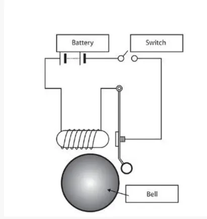
Solenoid : A chime doorbell uses a specialized sort of electromagnet called a solenoid. A solenoid is just an electromagnet where the coiled wire surrounds a metal piston. The piston contains magnetically conductive metal, so it can be moved backward or forward by the electromagnetic field.
Simulink Model For Doorbell :
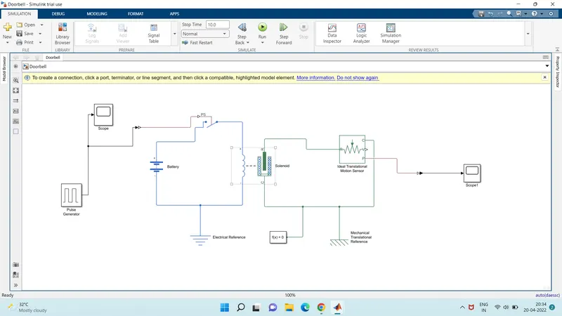
Explanation :
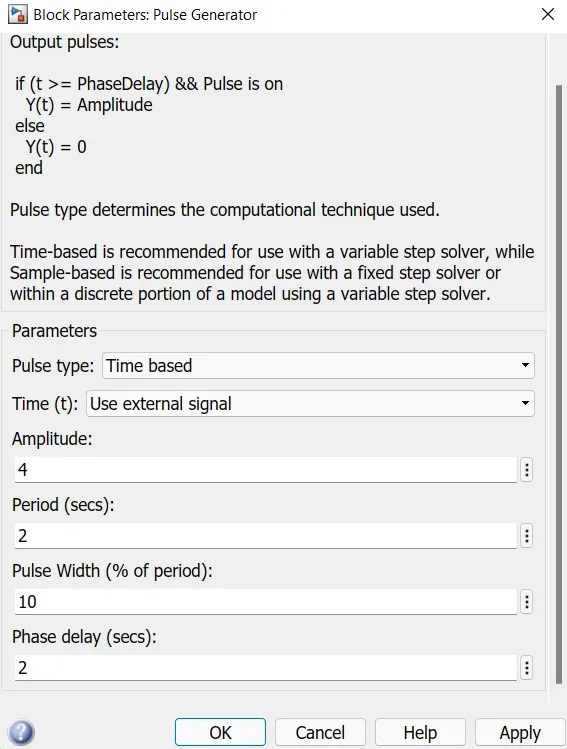
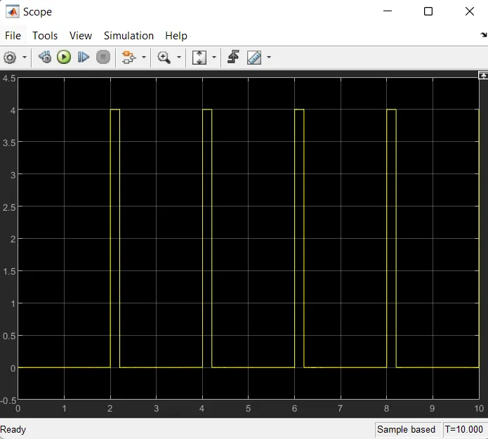
- Pulse Generator is used to provide square wave signal to switch to satisfy the condition, then switch is closed for 2 sec and then realeased
- Simulink PS converter is used to convert the simulink signal into physical signal
- Switch controlles the external physical signal
- battery gives the power
- Solenoid block is to convert the electrical energy into mechanical energy
- ideal translation motion sensor is used to sense the movement of the plunger and give the output to the scope
- PS simulink converter is used to convert physical signal into simulink signal
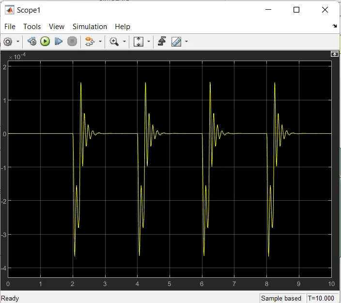
- scope is used to show the result of plunger movement to the observer in the graph
- solver configuration is use as to specify the solver parameters that model need before the simulation
- Mechanical translation references is used as reference connection for mechanical translational parts
Results :
Here are parameters for output pulses
Conclusion :
At The given input of time the pulse generator use as open and close the switch. when switch is closed the solenoid block recieves electric power from battery and the plunger moves and hit the bell and the sound generates.
#PART 2 :
Aim : To sense the temperature of a heater & turn on or turn off the fan using Themistor.
Objective : Sense the temperature of a heater & turn on or turn off the fan
Themistor :
Thermistors are temperature-dependent resistors, changing resistance with changes in temperature. They are very sensitive and react to very small changes in temperature. They are best used when a specific temperature needs to be maintained, and when monitoring temperatures within 50°C of ambient.
Given Condition :
-
Temperature source: 20 °C from 0 to 10 seconds, 27 °C from 10 to 30 seconds, 23 °C from 30 to 50 seconds
-
Fan conditions: ON if the temperature above 25 °C, OFF otherwise
Simulink Model :
Explaination :
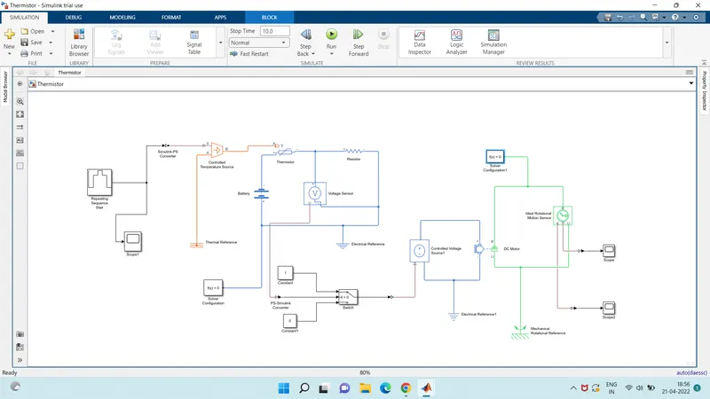
- As per given condition for time and tempreture gives value to the signal builder and configure as per our condition
- There is a simulink PS converter that converts the simulink signal into physical signal
- give the signal to the controlled tempreture source block which represents the ideal source of thermal energy that is powerfull enough to maintain specified tempreture diff across the source regardless of the heat flow consumed by the system
- this signal passes towards themistor which connected to the battery
- the voltage sensor is connected to a resistor which is used to measure the voltage as threshold value for the condition of our circuit
- as per fan condition that on if the tempreture above 25 deg otherwise off, we use switch and provide a threshold value
- if the signal value is greater than the threshold value then turn it on otherwise it will be turn off
Results :
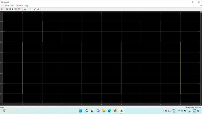
from 0-10 sec the fan is off because the tempreture is 293k which is below 298k, after 10 sec it will goes to 300k so the fan will turn on because the tempreture exceeds 298k.
After 30 sec the fan will turn off because the tempreture goes to 293k which is less than 298k.