Week -2
Q 1.)In the above arrangement, when the switch is closed the electromagnet receives electrical power from the battery and pulls the metal arm to hit the bell producing sound.
Create a situation where the switch is closed for 2 seconds and then released. Observe the physical movement of the plunger.
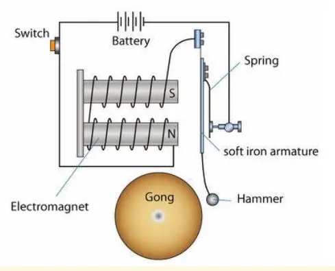
Doorbell: The electric doorbell is a simple circuit that triggers a sound on the completion of the circuit by pressing the button.
When the switch is pressed, the circuit loop is complete which causes the current to flow through the circuit. The arm which strikes the gong is connected to spring at one end and an iron ball at the other end. This is called a hammer or a striker. The arm is attached to an iron strip which is attracted to the electromagnet when the circuit is complete and the current flowing through it.
Solenoid: A solenoid is a type of electromagnet, the purpose of which is to generate a controlled magnetic field through a coil wound into a tightly packed helix. The coil can be arranged to produce a uniform magnetic field in a volume of space when an electric current is passed through it.
A solenoid is a coil of wire designed to create a strong magnetic field inside the coil. By wrapping the same wire many times around a cylinder, the magnetic field due to the wires can become quite strong. The number of turns N refers to the number of loops the solenoid has. More loops will bring about a stronger magnetic field.
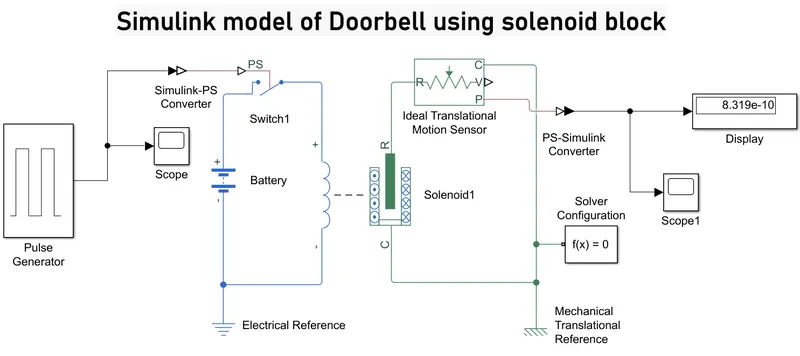
EXPLANATION :
- From the above governing circuit of a Doorbell, we know that we need a switch , solenoid, battery and a plunger.
- So, in order to get these entire component in simulink model we have to select the block that perform same action what the above device perform.
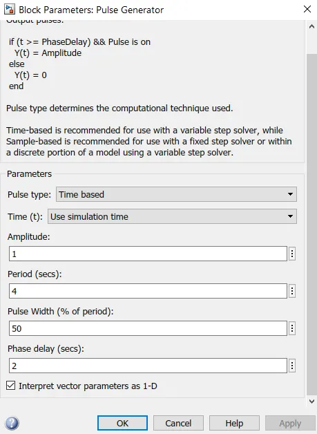
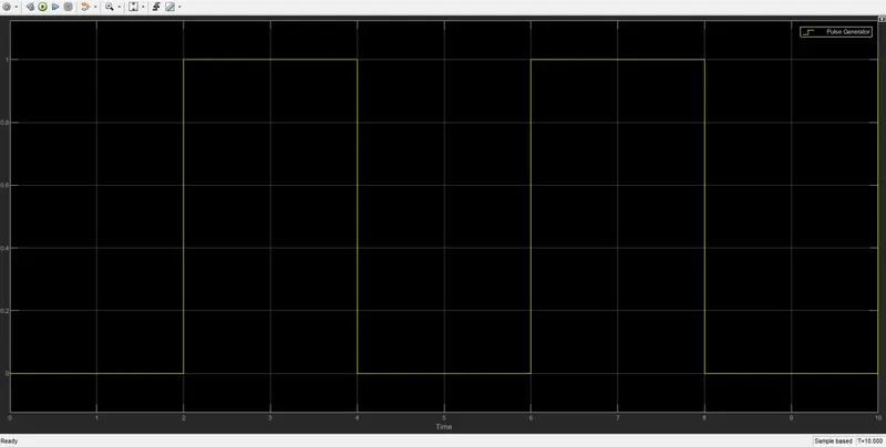
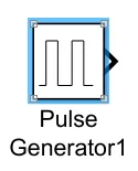 Pulse type determines the computational technique used. Time-based is recommended for use with a variable step solver, while Sample-based is recommended for use with a fixed step solver or within a discrete portion of a model using a variable step solver.An input signal is given according to given conditions
- (Amplitude = 1, Period = 4sec, pulse Widt =50%, Phase Delay = 2sec).
- Now first a "solenoid block" is taken to represent a solenoid in the model, then to represent battery we have taken "Battery Block" from the library Browser.
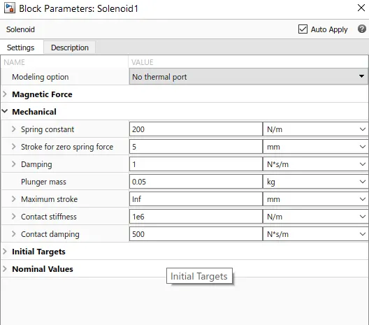
- Then this "Solenoid Block" & "Battery BLock" are connected to each other via +ve and -ve terminals.
- A "Switch Block"
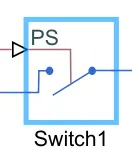 (The block represents a switch controlled by an external physical signal. If the external physical signal PS is greater than the threshold, then the switch is closed, otherwise the switch is open. The closed resistance is defined by parameter R_closed, and the open conductance is defined by parameter G_open. Both parameters must be greater than zero.) is placed between
 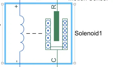 "Solenoid Blocks" (Solenoid converts electrical signals to mechanical signals.) and
 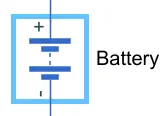 "Battery Block "and is connected with both blocks. and negative port of battry is connectiec to ground.
 - which is known as Electrical refrence Port.
 A model must contain at least one electrical reference port (electrical ground).
 - Now for switch to operate we need to provide Physical signal through "PS" port in the "Switch Block". The provided Physical signal should be greater than the threshold of the switch, for switch being close, or else it will be open.
- A Simulink-PS Converter
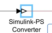 is used to convert the input Simulink signal into a physical signal.
 - A Switch is connected to battery and solenoid respectively as shown. If the external physical signal PS is greater than the threshold, then the switch is closed, otherwise, the switch is open.
- The Ideal mechanical translational motion sensor
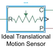 converts an across variable measured between two mechanical translational nodes into a control signal proportional to velocity and position. The physical signal ports V and P report the velocity and position, respectively, of port R relative to port C. The measured velocity is positive when the velocity at port R is greater than the velocity at port C it connected to
  it is Use it to connect mechanical translational ports that are rigidly affixed to the frame (ground).
 - A PS-Simulink Converter
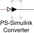 is used to convert the physical signal into a Simulink output signal.
 - The solver configuration block
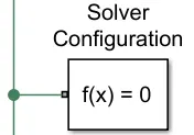 specifies the solver parameters that your model needs before you can begin the simulation.
 - Finally,
 Scope and
  Display are used to obtain the output plot.
RESUTLS :
SCOPE : PULSE GENRATOR
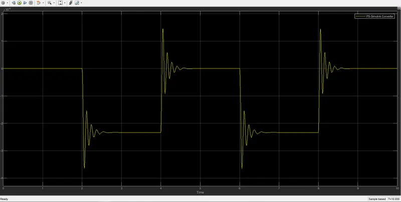
SCOPE : PS-Simulink Converter
Q2.) Use a thermistor to sense the temperature of a heater & turn on or turn off the fan as per the below conditions:
Temperature source: 20 °C from 0 to 10 seconds, 27 °C from 10 to 30 seconds, 23 °C from 30 to 50 seconds
Fan conditions: ON if the temperature above 25 °C, OFF otherwise.
A thermistor (or Thermal resistor) is defined as a type of resistor whose electrical resistance varies with changes in temperature. Although all resistors' Resistance will fluctuate slightly with temperature, a thermistor is particularly sensitive to temperature changes.
There are two types of Thermistors:
- NEGATIVE TEMPERATURE COEFFICIENT [NTC] : resistance decrease as temperature rises. an NTC are commonly use as Temperature Sensor, or in series with a circuit as an inrush current limiter.
- POSITIVE TEMPERATURE COEFFICIENT [PTC] : resistance increases as temperature rises. PTC thermistor is commonly installed in series with a circuit, and use to protect against overcurrent conditions, as resettable Fuse.
Explanation :
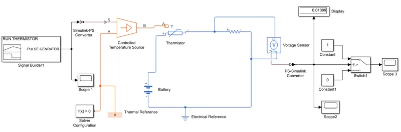
- To create a simple Fan cooling model using Thermistor,Battery,Resistor,Voltmeter, a logical switch which are basic component of the circuit we need in Simulink model.
- First to represent a
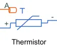 , a "Thermistor Block" is taken and placed in model. Now to represent Battery, a"Battery Block" is taken and the positive terminal of this block is connected to positive port of the "Thermistor Block". The thermistor block represents an NTC thermistor using the B-parameter equation.
 - Now to represent a
 , a "Resistor Block" is taken from Library browser and its positive port is connected to negative port of "Thermistor Block". The negative port of "Resistor Block" is connected to negative port of "Battery Block". Now a "Electrical Reference Block" is connected near the negative terminal of the "Battery BLock" which represent the Earthing of the real time circuit.
 - Now to represent a
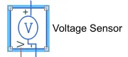 a "Voltage sensor Block" is connected parallel to the "Resistor Block", because to measure the voltage across a component, voltmeter should always connected parallel to that component.
 - Thus, we have completed our simple circuit Model, but we need some Physical Quantities to as Signal for Thermistor to work.
- In this case we need the Fan to get ON and OFF at different temperatures. So , to provide temperature , we have used
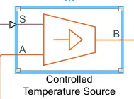 "Controlled Temperature Source Block" which will gives a specified temperature as output even though heat flow is more.
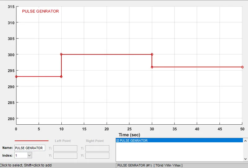
 - Now to give different temperature to this "Controlled Temperature Source Block" we need to send Temperature signals. To send these signals we have used a "Signal Builder Block" Which allows us to send any type of signal as inputs.
- We have to double click on
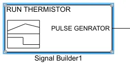 the "Signal Builder block" to set the signal configuration according to our requirement. it is renamed as RUN THERMISTOR.
RESULT OF SIGNAL BUILDER SCOPE 1:
Temperature source: 20 °C from 0 to 10 seconds, 27 °C from 10 to 30 seconds, 23 °C from 30 to 50 seconds
Fan conditions: ON if the temperature above 25 °C, OFF otherwise
GIVEN INPUTS :
At Point-1 - Time 0 sec - Temperature is 293k - 20 °C from 0 to 10 seconds,
At Point-2 - TIme 10 sec - Temperature is 293K
At Point-3 - TIme 10 sec - Temperature is 300K - 27 °C from 10 to 30 seconds
At Point-4 - TIme 30 sec - Temperature is 300K
At Point-5 - TIme 30 sec - Temperature is 296K - 23 °C from 30 to 50 seconds
At Point-6 - TIme 50 sec - Temperature is 296K
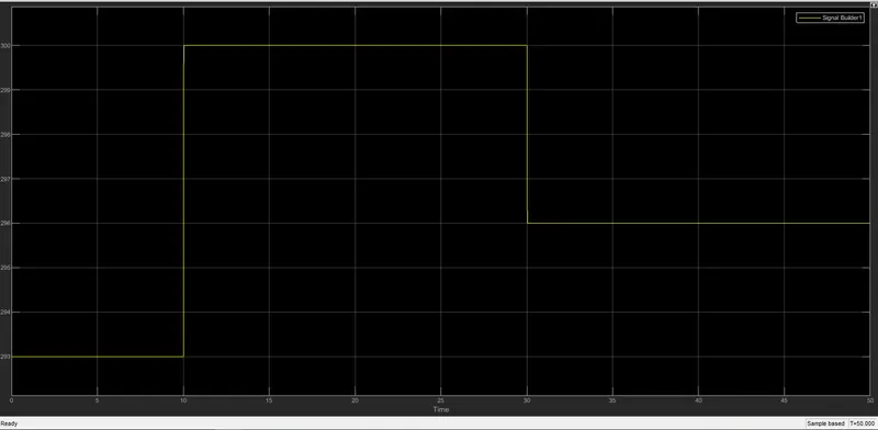
- We can see in the figure that how different temperatures are given at different time. So, thus we have created our signals and before connecting it to the "Controlled Temperature source block" we have to convert these Signals into Physical value. So, to do this we have used a "Simulink-PS Converter Block".
- So now the port "B" of "Controlled Temperature Source block" is connected to port 'A' of the "Thermistor block" and port 'A' of "Controlled Temperature Source Block" is connected to the "Thermal Reference block". In "controlled Temperature Source Block" a positive temperature difference causes the temperature at port 'B' to be greater than the temperature at port 'A'.
- Now the output of the "Voltage Sensor Block" is connected to "Scope Block" first and before connecting to the "Scope Block" a "PS-Simulink Converter" is used to convert Physical value to Simulink values.
- Now when we run the simulation and Double click on the "Scope Block" we will get the following Graph.
- From the above figure we can see that how voltage is changing with the change in temperature. Using this information, we can set condition for Fan to ON & OFF.
RESULT OF SCOPE 2:
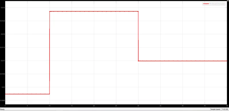
- If we observe the graph, we notice that from time 0 to 10 seconds when the temperature is 293K, Voltage is between 0.0095 and 0.01 and from time 10 to 30 seconds when the temperature is 300K, Voltage is between 0.0125 and 0.013 and from time 30 to 50 seconds when the temperature is 296K, voltage is nearly 0.011.
- As mention in the objectives fan should be On When the temperature is more than 25 degree Celsius i.e. 298.15K, from the above graph when voltage is more than 0.011 the Fan should get ON and when the Voltage is below 0.011, Fan should get OFF.
- This above Logic used to ON and OFF the Fan. To do this we have used a
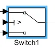 "Switch Block" that routes the Signal according to the conditions provided.
 - The center port of "Switch Block" is connected to output of "PS-Simulink Converter" which gives the Voltage values. The top port of the "Switch Block" is connected to a "Constant Block" of value '1'
 and the bottom port of the "Switch block" is connected to another "Constant Block" of value '0'
  .
. - The center port of "Switch Block" is the condition input which means that when the value from "Voltage sensor Block" is more than the Threshold value in the "Switch Block" then it will pass the value '1' Which we have specified in the top port of the "Switch Block". if the Voltage from the "voltage Sensor Block" is less than the Threshold value in the "Switch Block" then it will pass the value '0' Which we have specified in the bottom port of "Switch Block". Here it acts like a Transistor in Real time Circuit.
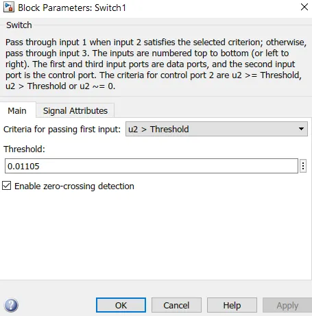
- To set the "Threshold value" of the "Switch BLock", we have to Double click on the "Switch Block" and then we can change the value of Threshold. Since we want to be ON only when the temperature is 300K so the Threshold value is given as {0.011}. so when the Voltage gets more than "0.011" the Switch will give value '1' as output which means Fan will be ON and when Voltage get less than 0.011 the Switch will give value '0' as output which certainly means Fan will get OFF.
- Now the output of "Switch Block" is connected to another "Scope BLock" to get
 FINAL results.
FINAL OUTPUT :
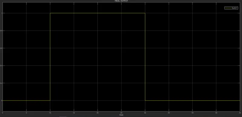
- By Double clicking the "Scope BLock" we can observe the above Graph. Here we can clearly see that when temperature is 300K the Fan is ON and at remaining temperature the Fan is OFF.
FINAL RESULT :
- Thermistor is used to sense the temperature of a heater & turn on or turn off the fan as per above conditions
- The FAN Conditions executed by SWITCH BLOCK and plotted in scope block.