Week -2
AIM:
- Make a Simulink model of Doorbell using solenoid block with the following details:
In the above arrangement, when the switch is closed the electromagnet receives electrical power from the battery and pulls the metal arm to hit the bell producing sound.
Create a situation where the switch is closed for 2 seconds and then released. Observe the physical movement of the plunger.
Assume remaining parameters.
2. Use a thermistor to sense the temperature of a heater & turn on or turn off the fan as per the below conditions:
Temperature source: 20 °C from 0 to 10 seconds, 27 °C from 10 to 30 seconds, 23 °C from 30 to 50 seconds
Fan conditions: ON if the temperature above 25 °C, OFF otherwise.
MODEL 1: CREATING THE SIMULATION MODEL FOR DOORBWLL USING A SOLENOID BLOck
THEORY:
- When we press the switch, we are basically closing the circuit and then the electric current is flown through the circuit.
- Then the electromagnet or the solenoid gets charged and it acts like a magnet due to which it pulls the near metal plunger towards it.
- the metal plunger then hits the gong and creates the sound for the bell
MODEL:
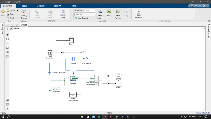
EXPLANATIONS:
We are gpoing to explain the mechanics of the model part by part
- PULSE GENERATOR: the pulse generator block generates square wave pulses at regular intervals. The block wavefoem parameters are amplitude, phase delay, pulse width and period determines the shape of the waveform.
- SCOPE: The scope displays the signal generated during simulation
- SPST Switch( Single-pole-Single-Throw Switch): A Single Pole Single Throw (SPST) switch is a switch that only has a single input and can connect only to one output. This means it only has one input terminal and only one output terminal. A Single Pole Single Throw switch serves in circuits as on-off switches. When the switch is closed, the circuit is on.
- BATTERY: used to store electric current
- SOLENOID: the block represents the electricsl charecteristics and generated force.This solenoid block represents the port R moving towards port C.
- MECHANICAL TRANSLATIONAL REFERENCE: it represents a reference point for all mechanical translational parts.
- SOLVER CONFIGURATION: It specifies the solver perimeters our model needs before begining the simulation.
- IDEAL MOTION TRANSLATIONAL SENSOR: it acts as amotion sensor in motion translational system.It represents a device which converts an across variable measured between two mechanical translational nodes into a controil signal proportional to velocity or position.
- PS-SIMuLINK CONVERTER: Converts the input physical signal to Simulink output signal.
WORKING of THE MODEL:
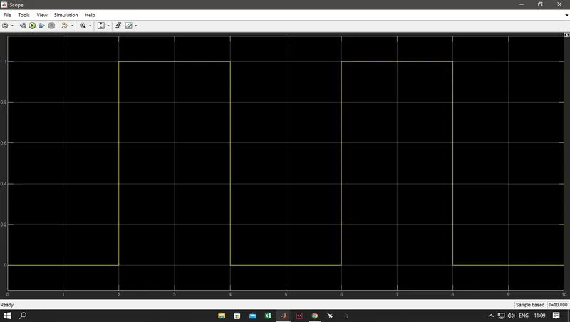
- PULSE GENERATOR: IT GENERATES WAVE PULSES AT REGULAR INTERVALS WITH 2 UNIT AMPLITUDE 4 SEC PERIOD, HAVING 50% PULSE WIDTH AND 2 SEC DELAY
- SCOPE: DISPLAYS SIGNALS GENERATED AS AN OUTPUT
- SIGNAL IS NOW CONNECTED WITH SIMULINK PS CONVERTER WHERE SIMULINK SIGNAL IS CONVERTED INTO PHYSICAL SIGNAL AND THEN IT IS SENT TO THE SPST SWITCH.
- AFTER THE SIGNAL IS RECEIVED, THE SWITCH COMPARES THE THRESHOLD VALUE AND IF ITS GREATER THAN IT THEN THE CIRUIT IS CLOSED OR ELSE IT REMAINS OPEN
- THEN THE SOLENOID GETS CHARGED AND IT PULLS THE PLUNGER WHICH WE HEAR AS THE RINGING OF THE BELL
RESULTS:
pulse value vs time
position vs time
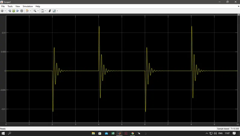
velocity vs time:
2. Use a thermistor to sense the temperature of a heater & turn on or turn off the fan as per the below conditions:
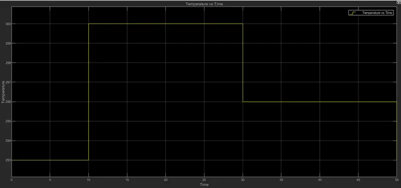
Temperature source: 20 °C from 0 to 10 seconds, 27 °C from 10 to 30 seconds, 23 °C from 30 to 50 seconds
Fan conditions: ON if the temperature above 25 °C, OFF otherwise.
THEORY:
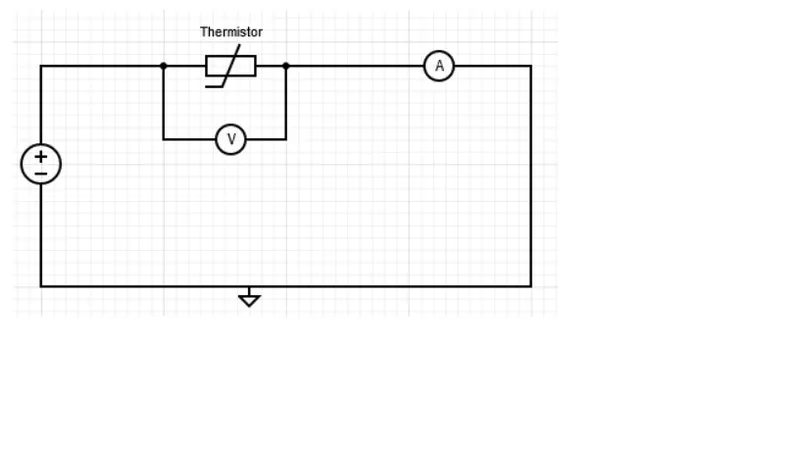
A thermistor is a type of resistor whose resistance is strongly dependent on temperature, more so than in standard resistors. The word is a combination of thermal and resistor. Thermistors are widely used as inrush current limiters, temperature sensors (negative temperature coefficient or NTC type typically), self-resetting overcurrent protectors, and self-regulating heating elements (positive temperature coefficient or PTC type typically). An operational temperature range of a thermistor is dependent on the probe type and is typically between −100 ⁰C and 300 ⁰C (−148 °F and 572 °F).
Depending on materials used, thermistors are classified into two types:
- With NTC thermistors, resistance decreases as temperature rises; usually due to an increase in conduction electrons bumped up by thermal agitation from the valence band. An NTC is commonly used as a temperature sensor, or in series with a circuit as an inrush current limiter.
- With PTC thermistors, resistance increases as temperature rises; usually due to increased thermal lattice agitations particularly those of impurities and imperfections. PTC thermistors are commonly installed in series with a circuit, and used to protect against overcurrent conditions, as resettable fuses.
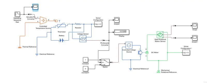
SIMULINK MODEL:
EXPLANATIONS:
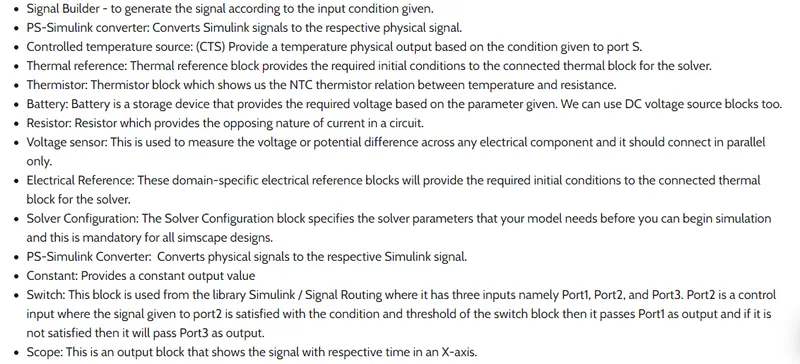
1.THEORY:
2.WORKING OF THE MAIN MODEL:
- here we use the repeating sequence stair to provide the time and the kelvin temperatures for the necessary observations
- then the signal is converted to a physical input signal by using simulink ps converter
- then a controlled temperature source is used to provide the temperature physical output based on the condition
- thermistor is further provided to get the relation between temperature and ressistance
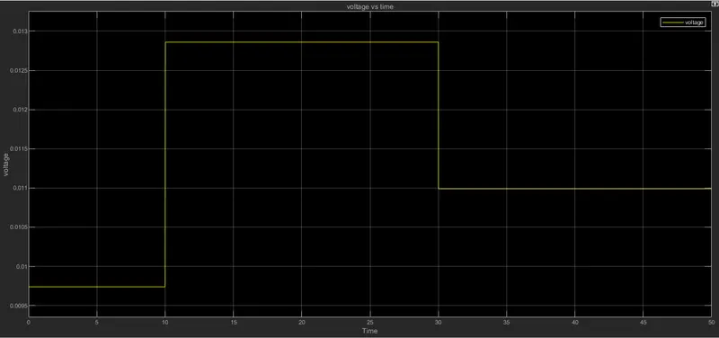
- as the temperature increases the thermistor ressistance decreases and the overall current in the circuit increases which leads to the increse in the voltage arround the ressistor
- then we note the voltage and accuire the graph for voltage vs time
- we also use a display block to get the threshold value
- after getiing the threshold value we use it in the criteria so that if the temperature is above 25 C or above 298 K the current will pass through the switch which will ultimately move the dc motor.
- if the voltage value is below the threshold value, the switch will not complete the circuit by closing and the motor will not function.
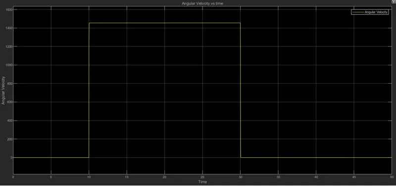
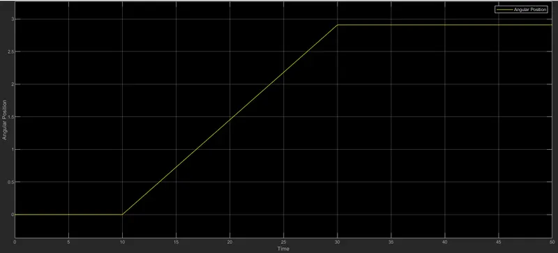
- to verify the outcome of the dc motor/universal motor, we have attached an ideal rtational motion sensor to it
- now the ps-simulink converter converts the physical signal into simulink signal which is then used to plot angluar velocity vs time graph and angular position vs time
3.RESULTS:
- TEMPERATURE VS TIME
- VOLTAGE VS TIME
- ANGULAR VELOCITY VS TIME
- ANGULAR POSITION VS TIME
4.CONCLUSION
- we have succesfully run the model of the doorbell using a solenoid block
- we have completed the model of thermistor to sense the temperature of a heater & turn on or turn off the fan
- we have also provided the graph for each and every observations for the two models and the necessary explanations are also provided for each of the model seperately
- thus in the 2nd experiment we can see that the fan is only turned on when the temperature reaches above 25 degree Celsius