Week -2
1) Doorbell simulation using solenoid block:
Description:
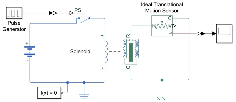
Making of Simulink model of solenoid doorbell using solenoid block from simscape library.
The circuit has battery, controlled switch & solenoid block. Switch is controlled using pulse generator block and it is to be switched on for 2 secs.
Solenoid movement is captured using translational motion sensor block and a scope block.
Step-wise explaination:
- An electric PS circuit is created containing a battery, PS switch, solenoid block & electrical reference.
- Pulse generator block is added with parameters: amplitude=1; period=4; pulse width=50; phase delay=0. It is connected to PS switch.
- Ideal translational motion sensor block is connected to R port of solenoid block. C port is attached to mechanical reference.
- The input from pluse generator & output of translational motion sensor block is given to scope.
Output:
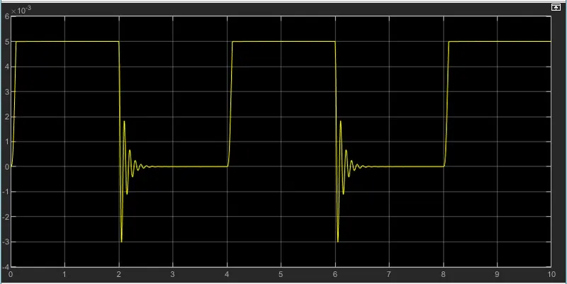
- When switch is turned on, plunger moves away from port C of solenoid block, and doesn't show oscillations because of contact damping.
- When switch is turned off, plunger moves to its previous position showing oscillations as seen in graph below.
2) Fan controlled by thermistor:
Description:
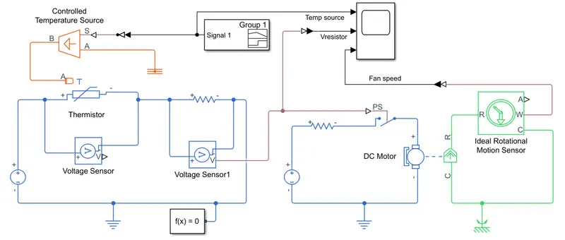
Using a thermistor to sense the temperature of a heater & turn on or turn off the fan as per given conditions.
A controlled temperature input is provided to thermistor A resistor is attached to it in series combination.
Voltage across the resistor is monitored and is used to turn on/off PS switch. The PS switch controls another electric circuit containing DC motor. The output of DC motor is measured using rotational motion sensor.
Step-wise explaination:
- Signal builder block is used to generate temperature values as given in the question.
This signal is then fed to controlled temperature source block, whose B port is connected ti thermistor & A port is connected to thermal reference block. - An electric circuit containing thermistor, battery and a resistor is made. Electrical reference and solver configuration is attached to it.
- Volatge accross the resistor is measured using voltage sensor block by connecting it in parallel configuration.
- The signal from voltage sensor is fed to PS switch which closes when the voltage is above 20 and opens otherwise.
This switch is conntected in a electric circuit containing a battery and a DC motor. - Output of DC motor is measured using ideal rotational motion sensor block, whose R port is connected to R port of DC motor & C port is connected to rotational reference.
- The input temperature from signal builder, voltage across resistor and DC motor rotational speed are given to scope block.
Output:
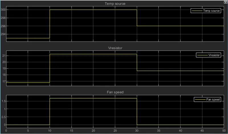
- Result shows that fan switches on when temp is above 25 degC and turns off when Temp becomes less than 25 degC