Week -2
AIM:
To make a Simulink model of Doorbell using solenoid block and sense the temperature of a heater by using a thermistor to turn on or turn off the fan as per the given conditions.
OBJECTIVES:
- Make a Simulink model for the doorbell using a solenoid block and observe the physical motion of the plunger.
- To sense the temperature of a heater by using a thermistor to turn on or turn off the gan as per the given below condition
- 20 °C from 0 to 10 seconds
- 27 °C from 10 to 30 seconds
- 23 °C from 30 to 50 seconds
The fan should be turned on if the temperature range is above 25 °C
SIMULINK MODEL OF DOORBELL:
Simulink model for Doorbell Is given below;
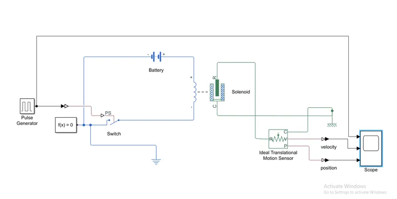
the .slx file of the above is given below in the google drive link;
Current version
previous version
EXPLANATION:
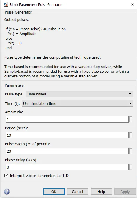
- Firstly, we need an inputs source so we chose a pulse generator block and configure the initial condition that we want and set it for 10 sec.
- Connect the pulse generator block by using a simulink-ps convertor to the switch which is in the circuit contains a battery and one part of the solenoid. The ground is connected to the ground with help of an electrical ground reference and a solver equation block.
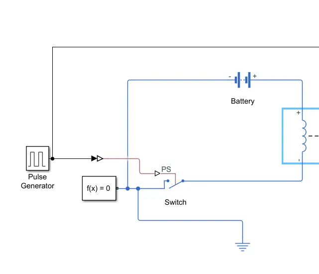
- The above circuit provides enough electric energy to make solenoid work when the input is positive(when the pulse generator gives input)
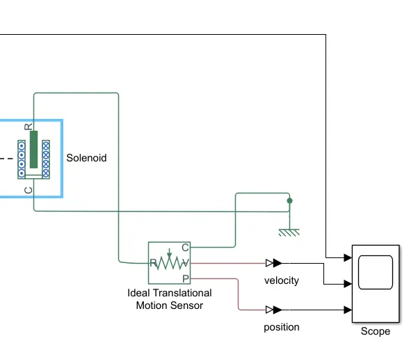
- the other part of the solenoid has two terminal which is for the output(R)and reference(C). Port R is connected to the ideal translational motion sensor as an input and port C is connected to the mechanical reference block.
- The ideal translation motion sensor has three output ports C, V and P for reference, Velocity and Position.
- port C was connected to the mechanical reference block, port V and P are connected to the scope block for recording the velocity and position of the plunger which is given below.
- Scope block recorded the output of the ideal translational motion sensor for the starting time to ending time in graph format for the velocity and position output of the ideal translation motion sensor and one extra graph for the pulse generator. The results are given below.
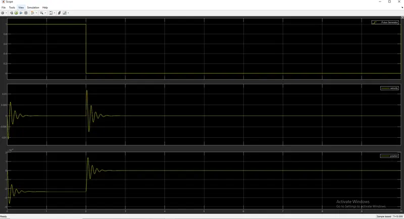
From the above graph, we see the potion of the plunger for the 2 sec of the closed-circuit at the beginning of this simulation.
SENSE THE TEMPERATURE OF A HEATER BY USING A THERMISTOR TO TURN ON OR OFF THE FAN:
Simulink model;
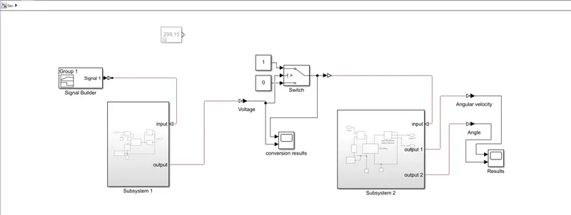
the .slx file of the above is given below in the google drive link;
current version
previous version
EXPLANATION:
Here we split the block diagram into 5 different parts
- Input
- Subsystem 1
- Intermediate system
- Subsystem 2
- Output system
Input
here we use the signal builder for producing the different amount of input in the different time span which is given below
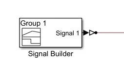
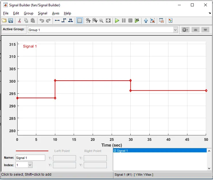
in this, we set the input range of y in different ranges for 3 different time spans. this input is actually the source for the controlled temperature source block in subsystem 1 by using Simulink-ps convertor.
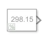
the commanded out constant block is for to get the voltage at the temperature range of 25 degree celsius to provide the condition (threshold) for the switch in the intermediate system part.
Subsystem 1
This subsystem 1 has several blocks to derive the resistance with respect to the temperature of the heating system and give the output as in the voltage form to the intermediate system.
the picture of those blocks are given below;
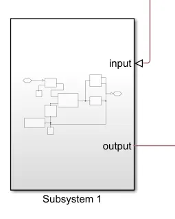
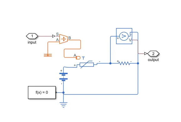
The above system contains one controlled temperature source which gives the output to the thermistor which is connected inside the circuit. the circuit contains a resistor, Solver block, Voltmeter, Battery and grounded with electrical reference block. The output of this subsystem is the voltmeter's readings.
Intermediate system
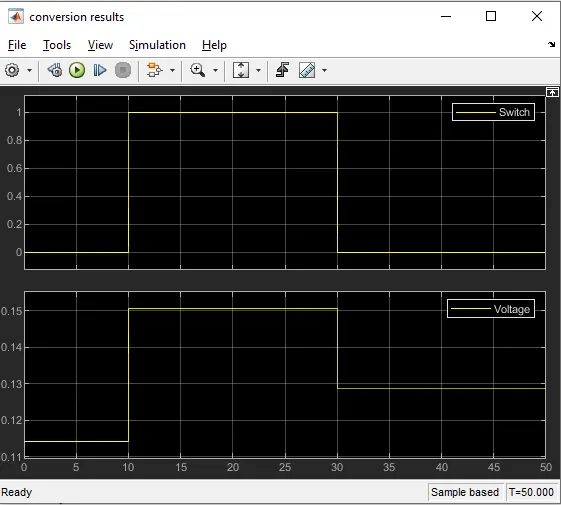
This system takes the input from subsystem 1 and by using the input it operates the switch with the applied condition. Also has a scope block to record the operation(results).
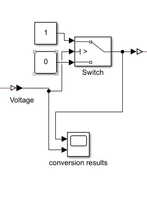
conversion results graph is given below;
Subsystem 2
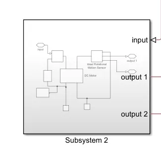
This system has a circuit of one input and two outputs for the operation of the dc motor with the help of the switch in the Intermediate system. the circuit contains one electric switch, voltage source and a dc motor which is grounded and the solver block is connected to the circuit.
it takes the inputs from the intermediate system and gives its outputs to the scope blocks in the output system
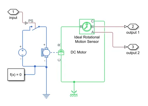
the output of this system is in the form of Angular velocity and angle from the rotational motion sensor which is placed and connected to the mechanical part of the dc motor.
Output system
this is just an output of the Angular velocity and Angle of the dc motor from the ideal rotational motion sensor in scope block(Results) with respect to time.
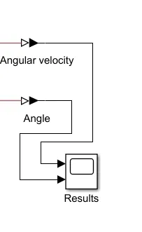
result of the above Simulink simulation is the graph of the conversion results scope block which is also given below;
CONCLUSION:
The Doorbell and actuation of the Fan using a thermistor were created and simulated successfully and also we got the result as per the condition.
REFERENCE: