Doorbell using solenoid block and thermistor to sense the temperature of a heater & turn on or turn off the fan.
simulink
aim:- Make a Simulink model of Doorbell using solenoid block .
Use a thermistor to sense the temperature of a heater & turn on or turn off the fan.
Doorbell
my smulation
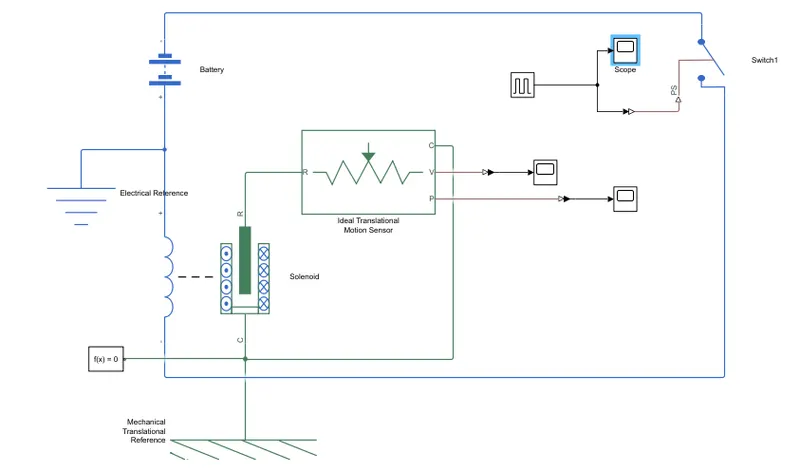
construction
battery: which provide electricity to run the process in doorbell.
switch: The block represents a switch controlled by an external physical signal. If the external physical signal PS is greater than the threshold, then the switch is closed, otherwise the switch is open.
pulse generator: this block provide the physical signal . where we take pause delay is 2 and the
Simulink-PS Converter : this converts the Simulink input signal to a Physical Signal.
scope: to display the graph
Ideal Translational Motion Sensor: This block measures velocity or displacement in a mechanical translational network. The sensor is ideal since it does not account for inertia, friction, delays, energy consumption, and so on.
Solenoid: comprised of a coil of wire, the housing and a moveable plunger (armature). When an electrical current is introduced, a magnetic field forms around the coil which draws the plunger in. More simply, a solenoid converts electrical energy into mechanical work.
solver configuration: Defines solver settings to use for simulation.
Electrical Reference: Electrical reference port. A model must contain at least one electrical reference port (electrical ground).
Mechanical Translational Reference:This block represents a mechanical translational reference point, that is, a frame or a ground. Use it to connect mechanical translational ports that are rigidly affixed to the frame (ground).
working
the negative end of the battery is connected to the switch which passes to te negative end of the solenoid.
and the possitive end is connected to the possitive end of the solonide .
an electric reference is added to the battery .
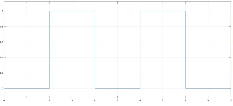
pulse generator is used to provide as an input to the switch at which time switch need to be on and off. with time delay of 2sec. ascope is added to it to see the time delay and phase delay.
solenoid is connected to machinical Translational refrence and the moving ing part of the solenoid is connected to the Ideal Translational
Motion Sensor which sense the motion ang gives the out put velocity and position of the motion .
where the port c is connected to the same port of the port c of solenoid with given machinical Translational refrence
an solver is added to choose which solution setting os to be selected.
as the curcit completed the an signal is send by the pulse generaton and the switch on and off due to which solenoid is magnatic motion is generated which is sense by the sonsor which display the position in the scope by using an PS-Simulink Converter.
giving input of time delay as 2 and period second of 4
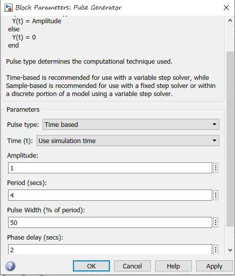
gramp meaning
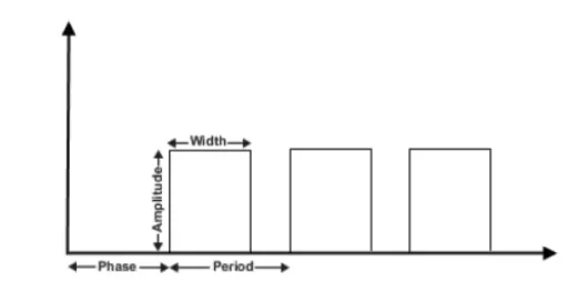
graph of pulse generator.
output graph of motion sensor where it sense the motion and and and give vibration as an sound.
THERMISTOR
A thermistor is a temperature-sensing element composed of sintered semiconductor material which exhibits a large change in resistance proportional to a small change in temperature. Thermistors usually have negative temperature coefficients which means the resistance of the thermistor decreases as the temperature increases.
in this we are using thermistor in with temperature increase so resistance will also increase.
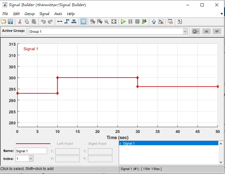
INPUT
point 1-time0sec- temperature 293k,
point 2-time10sec- temperature 293k,
point 3-time10sec- temperature 300k,
point 4-time30sec- temperature 300k,
point 5-time30sec- temperature 296k,
point 6-time50sec- temperature 296k,
starting
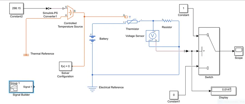
FIRST constant is used with 298.15 this is because we need to know what is the voltage at the 298.15 (25 °C) TO provide the condition to the switch.
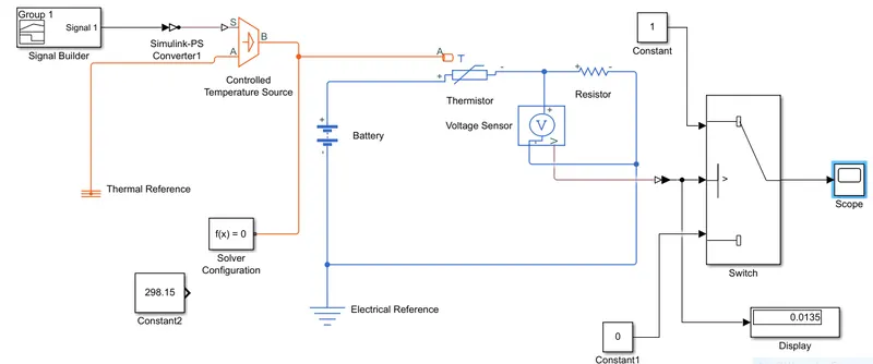
final simulink
working
signal builder will give the input to the simulink to ps convertor
controlled temperature source will take the input from s and give the out put from B and A will be added to thermal refrence.
solver is added to make the desigion to choose the solution.(at any point)
output B of controlled temperature source will go the thermistor .
resistor is added in series with (+) of resistor to (-) of thermistor and (-)resistor is connecter to battery.
voltage sensor is added to te resistor in parallel to sense the change in voltage.
thermisor will sense the temperature and due to change in temperature resistance will be change and due to which voltage will change this change in voltage will be will give the signal to the switch and it will provide the output in scope.
constant condition is given 0 switch will be off and 1 switch will be on.
(see the sequence of my simulink to avoid error)
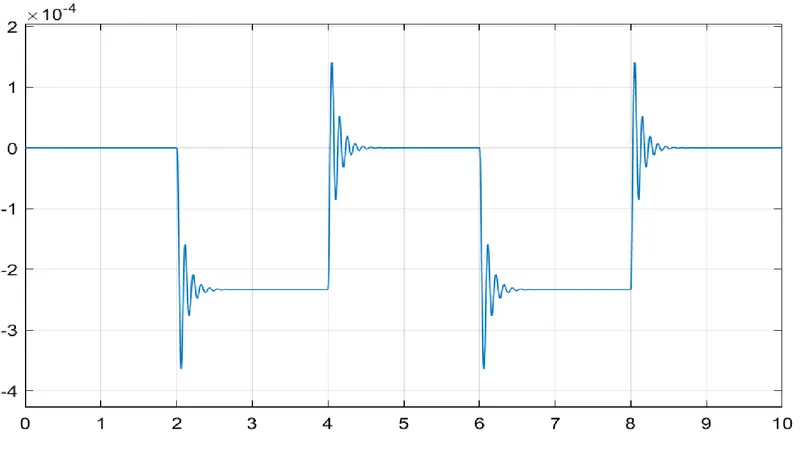
OUT PUT GRAPH
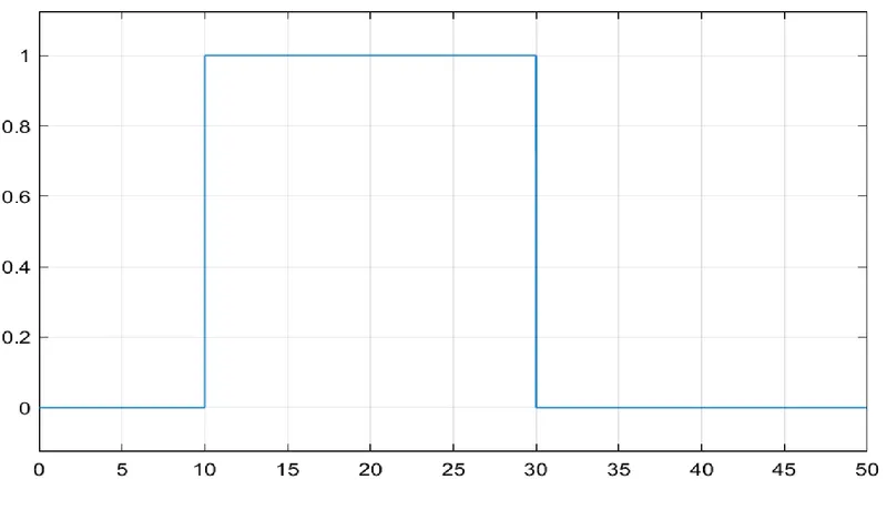
from 0-10 the fan will be off because temp is 293k. after 10 sec temp is 300k so the fan will turn off. again after 30 sec fan will turn off.
conditions
1
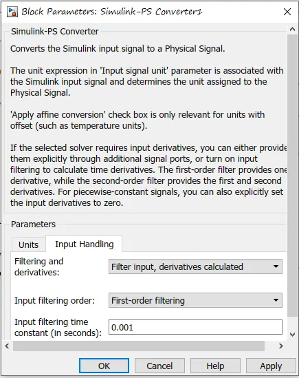
change in the Simulink-PS Converter1 because we are giving multipal input by Signal Builder.
2
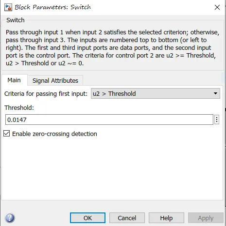
providing display output value to the switch .
refrence
https://www.youtube.com/watch?v=HpTp227586s
thank you