Week -2
AIM
- Make a Simulink model of doorbell using solenoid block.
- Use a thermistor to sense the temperature of a heater and turn on or turn off the fan.
OBJECTIVE
For doorbell
- Create a situation where the switch is closed for 2 seconds and then released. Observe the physical movement of the plunger.
For fan
- Temperature source should be 20from 0 to 10 seconds,27 from 10 to 30 seconds,
23 from 30 to 50 seconds. Fan conditions should be on if the temperature is above 25. Off otherwise.
THEORY
Solenoid
- A solenoid is a type of electromagnet formed by a helical coil of wire whose length is substantially greater than its diameter which generates a controlled magnetic field. The coil can produce a uniform magnetic field in a volume of space when an electric current is passed through it.
- The solenoid simply works on the principle of electromagnetism. When the current flow through the coil magnetic field is generated, if you place a metal core inside the coil, the magnetic lines of flux are concentrated on the core, increasing the coil's induction compared to the air core.
Thermistor
- A thermistor was first discovered by Michael faraday in 1833 on a silver sulfide which showed a behavior of decrease in resistance when temperature increased.
- A thermistor is a semiconductor with more resistance capacity than a conducting material and less than insulating material. Its electrical resistance varies with the change in the temperature or thermally sensitive resistor. There are mainly two types of thermistors, namely the negative temperature coefficient (N T C) and positive temperature coefficient ( P T C).
- Thermistor’s relation with temperature also depends on the material in which it is made. A negative temperature coefficient (N T C) thermistor will decrease its resistance value when temperature increases whereas a positive temperature coefficient will increase its resistance when temperature increases. the electronic symbol of the thermistor is given below.
- N T C thermistors are widely used in industries for different applications like temperature measurements, temperature control, etc. P T C is mostly seen in circuit protection, current-limiting resistors.
DOORBELL MODEL
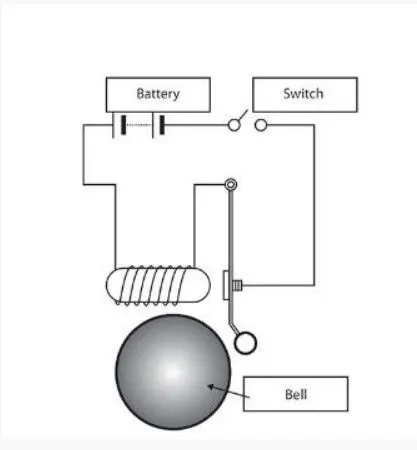
figure 1.1 doorbell
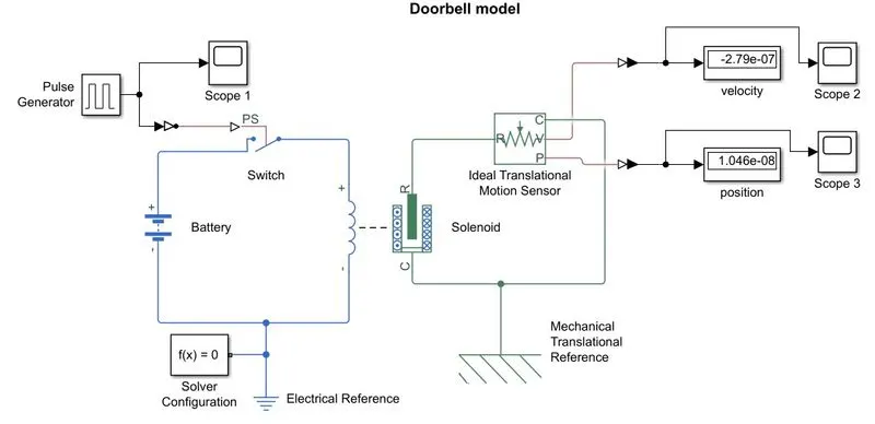
figure 1.2 doorbell model
google drive link- click here for the doorbell simulation file.
RESULT
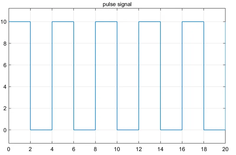
figure 1.3 pulse signal
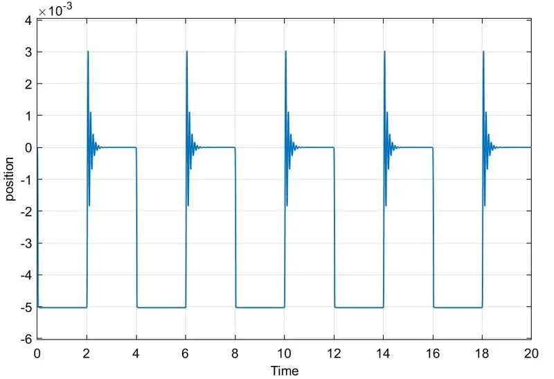
figure 1.4 bell plunger position
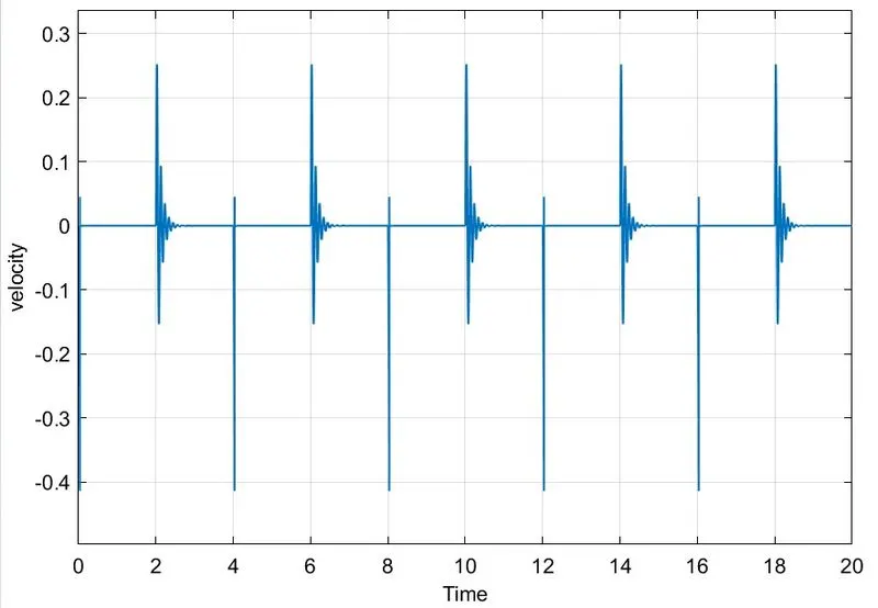
figure 1.5 bell plunger velocity
EXPLANATION OF DOORBELL
- Here principle of working is that when the doorbell switch is pressed, the electrical circuit closes and results in the generation of a magnetic field. The magnetic field attracts the iron bar, which pulls the metal arm to hit the bell producing sound.
- In the model there are two loops, one is electrical and the other is a mechanical loop, electrical loop consists of a battery, switch, and solenoid’s coil part.
- As per the question here switch is closed for 2 sec and released these signals created through pulse generator with settings of the period is equal to 4 and pulse width is changed to 50 % of the period. These signals are passed to the electric loop through a switch physical signal port.
- While signal passing to the switch the data is needed to convert to physical signal. So Simulink-ps converter is connected in between switch and pulse generator. In Simulink-ps converter change settings to provide filter input, derivatives calculated, for solving unnecessary error and input signal smoother.
- Input signal can check through the scope, which is connected to the pulse generator.
- Solver configuration and electrical reference are connected in the electrical loop for specifying the solver parameter and providing the required initial conditions to the electrical block for the solver.
- Next loop is mechanical, it consists of a solenoid plunger part, ideal translational motion sensor.
- Here ideal translational motion sensor senses the translational motion of the plunger according to the input signal from the pulse generator.
- Mechanical translational reference is connected to the mechanical loop for getting initial conditions of a mechanical block for the solver.
- The translational motion sensor gives velocity and position output through port V and P respectively. Convert these physical signals to Simulink signals by ps-Simulink converter and to get output at display and shows with respect to time through scope.
- In the result, clearly shows the position of the plunger hitting in each period.
FAN MODEL
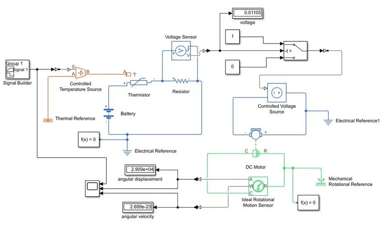
figure 2.1 fan model
google drive link- click here for fan simulation model file
RESULT
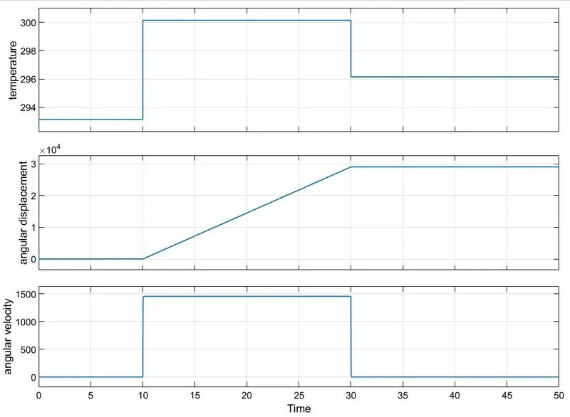
figure 2.2 result of fan movement
EXPLANATION OF FAN PROBLEM
- Here the objective is to operate a fan. The fan is in ‘on’ condition if the temperature is above 25 and otherwise ‘off’ condition.
- In the model mainly there are three loops which are two electrical loops and one mechanical loop. The first electrical loop is to generate a voltage according to the temperature signal. The second electrical loop is to provide or maintain the specified voltage to the DC motor coil part. The third loop is a mechanical loop of the DC motor rotor part.
- As per the question, temperature signals are created using signal builder block with 50-sec duration and temperature with respective kelvin values as all the thermal blocks will be in kelvin by default controlled temperature source is used to provide a temperature signal to first electrical loop.
- Signal builder is connected to the temperature source through Simulink-ps converter to convert signal to physical signal and provide filter input, derivative calculated, to solving unnecessary error and to became input signal smoother.
- Thermal reference also connected to the controlled temperature source for required initial conditions to the connected thermal block for the solver.
- In the first electrical loop consist of a thermistor, resistor, and battery. Thermistor receives temperature signal through port A. According to the temperature, the resistance value of the thermistor changes then the current flow changes in the loop, and voltage also changes. This voltage is measured through a voltage sensor which is connected parallel to the resistor.
- These voltage sensor gives output as a voltage through port V. This physical signal is converted to Simulink signal and connected to display and switch.
- As per question the fan needs to on the temperature is above 25 and otherwise ‘off’ condition. These criteria are achieved through switch settings, that is the switch’s threshold voltage is set to the voltage when the temperature at 25 ( 298.15 K) . that is, if the external physical signal PS is greater than the threshold, then the switch is closed, otherwise the switch is open.
- Then these signals passed to the second electrical loop through Simulink-ps converter and physical port of controlled voltage source.
- Controlled voltage source block which maintains the specified voltage at its output regardless of the current passing through it. The second electrical loop consists of a controlled voltage source and a DC motor coil part.
- Electrical reference is provided for both electrical loops to provide the required initial conditions to the connected electrical block for the solver.
- The third loop is a mechanical loop that consists of a DC motor rotor part and an ideal rotational sensor. Here the rotor part of the motor is rotating as per the voltage.
- Mechanical rotational reference is connected to the mechanical loop for getting initial conditions of a mechanical block for the solver.
- Separate solver configuration is connected in both the first electrical loop and mechanical loop to specify the solver parameter.
- The angular velocity and angular displacement is measured through the ideal rotational motion sensor through port W and A respectively. This physical signal is passed to the ps-Simulink converter and displayed through the scope.
- In the result, clearly shows that the angular velocity is high only in the interval of 10 to 30 seconds and the remaining time, angular velocity remains zero. That is at the time interval 10- 30 sec the temperature is 27, as per the condition the motor or fan is in ‘on’ condition.
CONCLUSION
- Doorbell model maked and the physical movement of the plunger is shown in the scope.
- Operated the fan using thermistor as per temperature values, model is created and output angular velocity is shown in the scope.