Week -2
1.
Model:
Pulse:
Explanation:
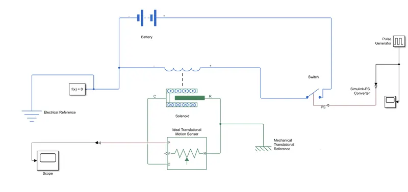
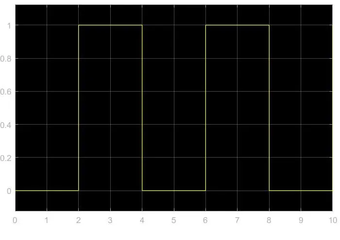
- The simulink model of a door bell is created by using a solenoid block, as per the given situation where switch is closed for 2s.
- The switch is controlled by using the pulse generator which is connected to the switch via simulink to ps convertor.
- The total time taken for the simulation is 10s.
- A battery is used as the power source for the doorbell.
- The positive and negative terminals of battery and solenoid are connected, with the switch in between.
- An electrical reference is also connected to the circuit along with a solver configuration block.
- The R terminal of the solenoid is connected to a ideal translational motion sensor and the C port of both the blocks are connected to mechanical translational reference.
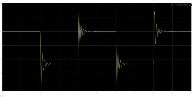
- The position of the plunger is detected by the sensor and it is shown using a scope block via ps to simulink convertor.
- The parameters of the solenoid are kept as default with damping coefficient as 1 and the results are shown as below.
Output:
2.
Model:
Parameters:
Explanation:
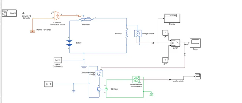
- The simulink model is created by using a thermistor to sense the temperature of a heater & turn on or turn off the fan as per the conditions.
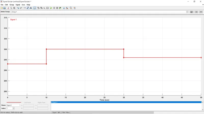
- The given conditions of change in temperature is created by using a signal builder as shown in the above figure.
- The signal builder acts as input for the controlled temperature source and is connected by using a simulink to ps convertor by changing it's parameters to take signal as input and a thermal reference is connected to the other port.
- The thermistor takes input from the source and the output is given to the electric circuit with a battery, resistor, electrical reference and a voltage sensor.
- The output of the voltage sensor is displayed and sent to the switch via ps to simulink convertor.
- The threshold value of the switch is determined by the displayed voltage value i.e 0.01099
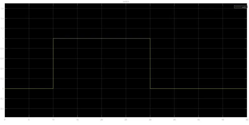
- The switch is connected to a scope and gives 1 as output when on and 0 when off.
- The output of the switch is taken into another circuit of a DC motor and the DC motor runs when the switch is on.
- The parameters of the DC motor are kept as default and the output is obtained by using a ideal rotaional motion sensor block.
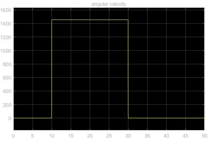
- The outputs of the switch and fan are given below in graphical form.
Output:
switch
fan