Simulink model of Doorbell using Solenoid Block.
1. Make a Simulink model of Doorbell using solenoid block with the following details:
In the above arrangement, when the switch is closed the electromagnet receives electrical power from the battery and pulls the metal arm to hit the bell producing sound. Create a situation where the switch is closed for 2 seconds and then released. Observe the physical movement of the plunger. Assume remaining parameters.
The solenoid in simple terms converts the electrical energy into mechanical energy. It comprises of a coil of wire and a plunger. When an electric current passes through the coil, a magnetic field is formed around the coil, which moves the plunger.
In case of a door bell, connecting the switch allows the current to pass through the circuit to the coil of wire, which in turn creates a magnetic field to move the plunger, causing a pull action on the arm, and hence hitting the bell producing the sound.
The Simulink model is as follows :
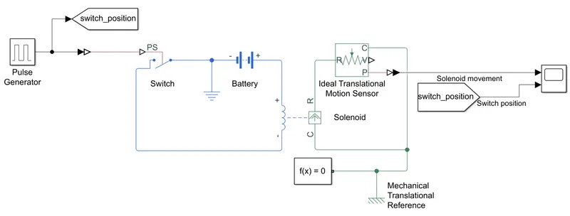
The input physical signal is sent to the switch. For the switch ON position a physical signal of magnitude 1 is sent to the switch block, and for the OFF position, the physical signal of magnitude 0 is sent to the switch. Hence the threshold of the switch is set to anywhere less than 1 (0.5 in this case is the default threshold value). A Battery of 12V is used, the rated voltage of the solenoid is also changed accordingly. To capture the movement of the plunger, the Ideal Translational Motion Sensor is used, and the sensed position is plotted using the Scope block.
The translational motion of the solenoid plunger is plotted as the output (in meters) . The following plot indicates the input physical signal and the output required. The model is simulated for 20 seconds.

It can be observed that, as and when the switch is in ON position (input physical signal = 1), the plunger moves, and hence the arm hits the bell producing the sound. The gradual movement of the plunger is observed in the slope of the output, as it takes around 0.6 seconds for the plunger to fully extend. A positive current from the electrical + to - ports results in a negative force (i.e. pulling force) acting from the mechanical C to R ports, hence the output plot indicates the movement of the plunger in the negative direction. On the other hand, when the switch is in OFF position (input physical signal = 0), the plunger returns back to the original position, and hence the arm comes back, and the bell sound stops.
Use a thermistor to sense the temperature of a heater & turn on or turn off the fan as per the below conditions:
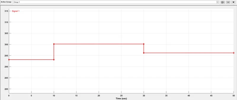
Temperature source: 20 °C from 0 to 10 seconds, 27 °C from 10 to 30 seconds, 23 °C from 30 to 50 seconds. Fan conditions: ON if the temperature above 25 °C, OFF otherwise.
The model is built to turn ON and OFF the fan depending on the temperature of the heater. The real-time temperature data is fed through a signal builder. The input temperature signal is as follows :
The Simulink model is as follows :
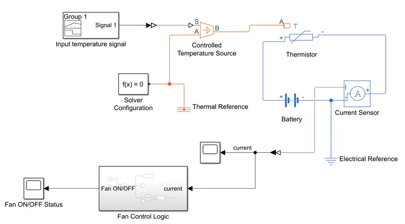
The temperature signal is sent to the controlled temperature source. The port A of the temperature source is connected to the thermal reference. The output from the temperature source is given into the thermistor. A thermistor is a resistor, whose temperature changes with temperature, due to which it can be used to measure the temperature based on the resistance value. The thermistor used is a NTC (Negative temperature Coefficient) thermistor, which means the as temperature increases, the resistance decreases. The resistance of the thermistor as a function of temperature is given by the following equation :
`R(T) = R_0* e^(B*(1/T - 1/T_0))`
Where `R_0` is the nominal resistance at the reference temperature `T_0`, `B` is the characteristic temperature constant. The `R_0` value by default is set to `1kOmega`, and the value of `B` is set at 3500 K.
In the model, since the resistance cannot be measured directly, the current is measured using the current measuring sensor. Then the voltage is divided by this current value to determine the resistance. The threshold value for 25 degrees is determined initially by setting the temperature to be 25 degree Celsius, and the resistance value is recorded (which is 1002 ohms in this case).Using this the fan control logic is formed as shown below.
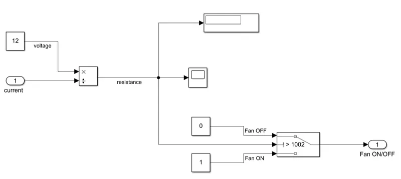
As the temperature increases beyond 25 degrees, the resistance will drop, and then the Fan turns ON, on the other hand, when the temperature drops, the resistance increases, when the resistance increases beyond the set threshold the fan turns OFF.
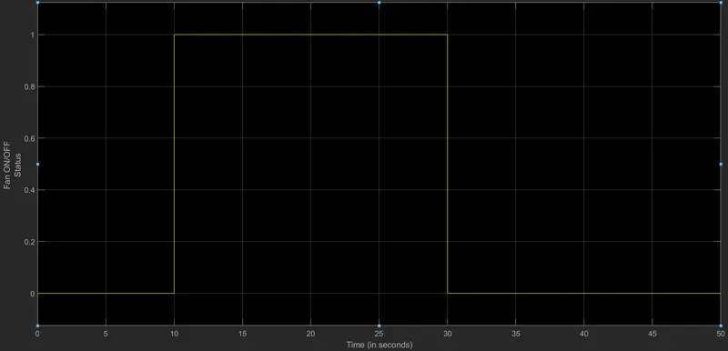
The Fan ON/OFF status is plotted as follows, and is observed that whenever the temperature increases beyond 25 degrees (between 10 - 30 seconds in the given scenario), the Fan turns ON (signal value =1), and when the temperature is less than or equal to 25 degrees, the Fan turns OFF (signal value =0).
The google drive link containing both these simulink model is as follows :
https://drive.google.com/drive/folders/1LJE1HY04lTxeeaWJ6-9qkfg2nTpbXd7q?usp=sharing.