Week -2
- Make a Simulink model of Doorbell using solenoid block with the following details:
In the above arrangement, when the switch is closed the electromagnet receives electrical power from the battery and pulls the metal arm to hit the bell producing sound.
Create a situation where the switch is closed for 2 seconds and then released. Observe the physical movement of the plunger.
Assume remaining parameters.
Ans. Explanation of the model:
Basic components used to generate a simple doorbell circuit are:
1. Battery
2. Switch
3. Solenoid
4. A Bell with plunger
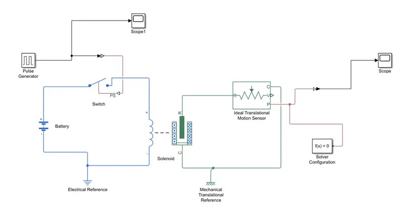
- Starting with first placing the 'Solenoid' and 'Battery' blocks connected together via positive and negative terminals.
- In between the 'Solenoid' & 'Battery' block there is placed a 'Switch' block connected to both.
- For this switch to operate, a physical signal 'PS' port is passed through it. The provided signal should be greater than the threshold of the switch which is closed or else it will open.
- To provide earthing for the circuit for the battery, switch and solenoid pathway, an 'Electrical Reference Block' is connected with the '-ve' port of the 'Battery' Block.
- Inside the 'Solenoid' block, 'R' and 'C' are two variables that represent plunger and fixed point respectively.
- 'R' of solenoid is connected to 'R' of 'Ideal Translation Motion Sensor Block', that senses the position of the plunger in the 'Solenoid Block' and gives the output.
- In this 'Ideal Translation Motion Sensor Block', 2 outputs 'V' & 'P' represent the velocity and position of plunger. The velocity of the plunger is not required, hence only 'P' gives the position of plunger as required.
- 'C' in 'Ideal Translation Motion Sensor Block' is mechanical translation conserving port, ie the mechanical process starts from 'R' and end at 'C' and again starts at 'R' and the cycle repeats.
- Also, this 'C' is connected to 'Mechanical Translation Reference' block that represents a fixed point in real time.
- 'C' of solenoid block also connected to this 'Mechanical Translation Reference' as a fixed point for the solenoid.
- The physical values of port 'P' of 'Ideal Translation Motion Sensor Block' were converted to simulink value using the 'PS-Simulink Converter' block that is connected to the 'Scope Block' which generates a graph for change in position of plunger from port 'P' of Ideal Translation Motion Sensor Block'.
- For proving the physical signal to operating the switch, a 'Pulse generator block' was used to generate a continuous square pulse.
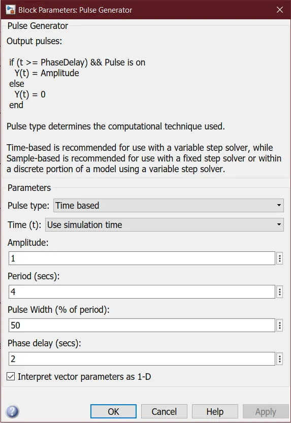
- From above figure, input values were '4', pulse width '50', phase delay '2' & amplitude default is '1'. Here, initial pulse will be zero and phase delay of 2 seconds until it reaches '1' as amplitude was inputed as '1'. Now, the pulse width is half of period, so next 2 secs the amplitude will be '1' only and then it comes down to zero at 4th second and then it stays at zero for next 2 secs thus completing period of 4 secs.
- So start to end pulse is 4 seconds of time period. 2 seconds rest and 2 seconds at '1' and then the cycle continues.
- To this 'Pulse Generator Block' a 'Scope Block' is connected to see how the pulse is generated.
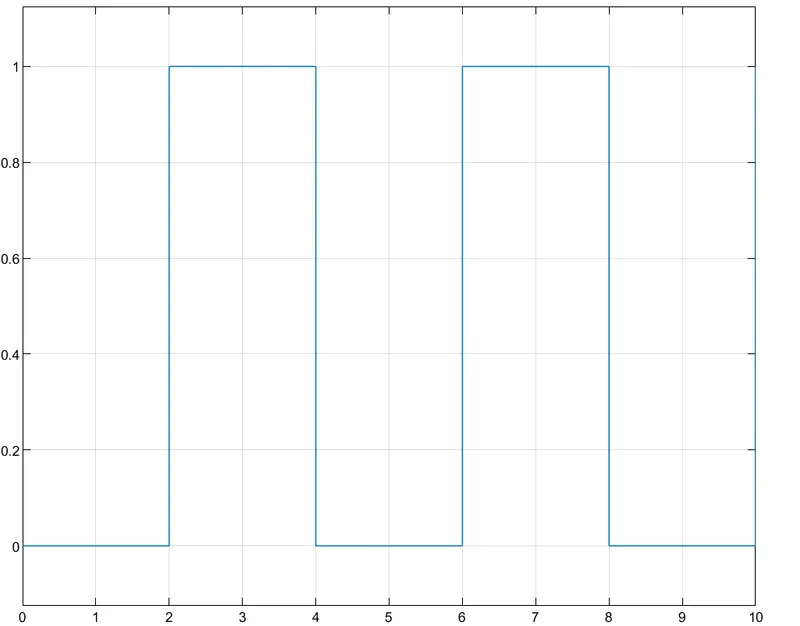
- By clicking the 'Scope1' block the above figure is obtained. X-axis represents time and Y-axis represents amplitude.
- The switch closes when it becomes zero and the switch opens when it becomes one.
- Th port 'P' of 'Ideal Translation Motion Sensor Block' is connected to 'Scope' block and 'Solver Configuration Block' which generates the equations and solves the model internally to give the output.
- Click on 'Scope' block connected to 'Ideal Translation Motion Sensor Block' to get the results.
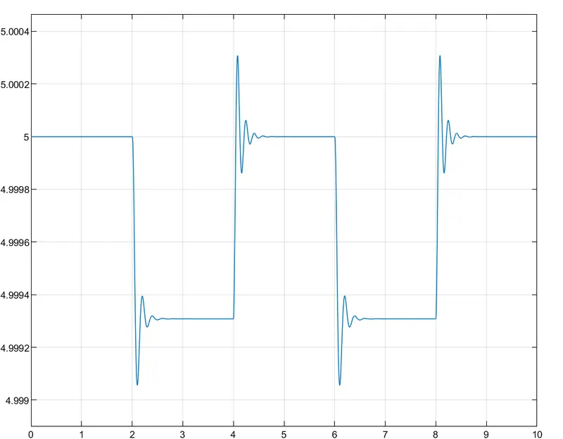
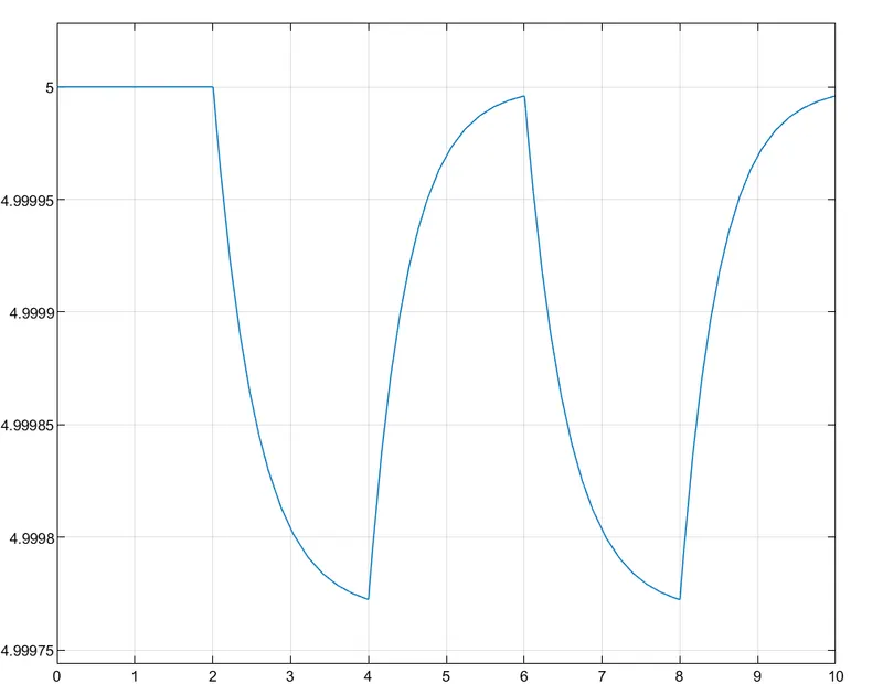
- X-axis represents time (secs) and Y-axis represents the position of plunger (mm)
- Initial position of plunger '5' as from the pulse generator block, pulse generated at '2' and so the position of plunger changes at time 2 secs until pulse amplitude is '1'
- Again, as the amplitude of the pulse becomes zero, the plunger returns to it's initial position and the cycle continues
- Observed that there is change in position of the plunger and some changes in waves at the start of changes in position.
- The waves are due to recoil of the spring and can be reduced by reducing the spring constant value and damping coefficient in the 'Solenoid' block for a much smoother graph to be obtained as shown below.
2. Use a thermistor to sense the temperature of a heater & turn on or turn off the fan as per the below conditions:
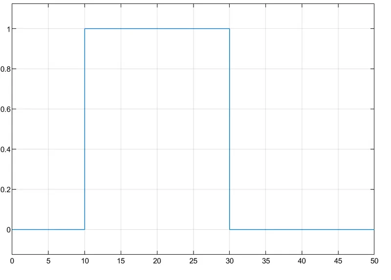
Temperature source: 20 °C from 0 to 10 seconds, 27 °C from 10 to 30 seconds, 23 °C from 30 to 50 seconds
Fan conditions: ON if the temperature above 25 °C, OFF otherwise
Ans.
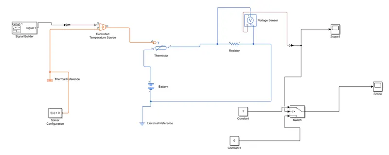
Explanation of the model:
Basic components used to create a Simple Cooling Fan Model using Thermistor are:
1. Battery
2. Thermistor
3. Resistor
4. Voltmeter
5. Logical Switch
- 2 Blocks are placed initially, 'Thermistor Block' and then a 'Battery Block' and +ve port of this block is connected to +ve port of thermistor.
- 'Resistor Block' is then placed and +ve port of this block is connected to -ve port of thermistor block, and -ve port of this resistor is connected to -ve port of the battery block.
- 'Electrical Reference Block' is connected near to -ve port of battery block that represents the earthing of this circuit
- For a voltmeter, a 'Voltage Sensor Block' is connected parallel to the 'Resistor Block' in order to measure the voltage
- For the fan to get ON and OFF at different temperatures. To provide temperature, used 'Controlled Temperature Source Block' that only gives a specified temperature as output.
- To give different temperatures, different signals need to send so 'Signal Builder Block' is used.
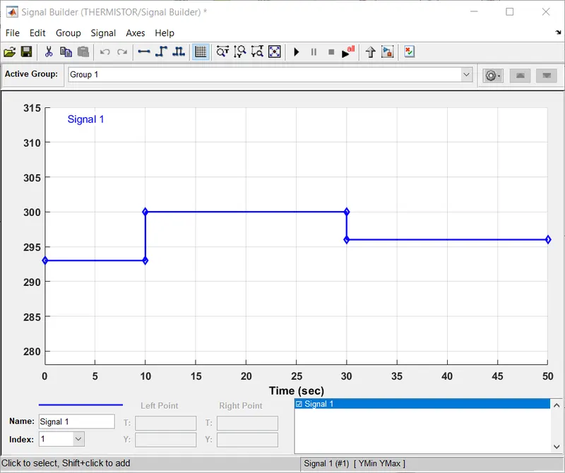
- Here, the values of 'x' and 'y' are input and the temperature as given above the signals are generated and it can be seen different temperatures are given at a different time and for these signals to be converted to a physical value, a 'Simulink-PS Converter Block' is used.
- The output of of 'Voltage Sensor Block' is connected to 'Scope' block first, and before connecting to the 'Scope Block' a 'PS-Simulink Converter' is used to convert the physical value to Simulink values.
- The 'Scope Block' gives the below graph
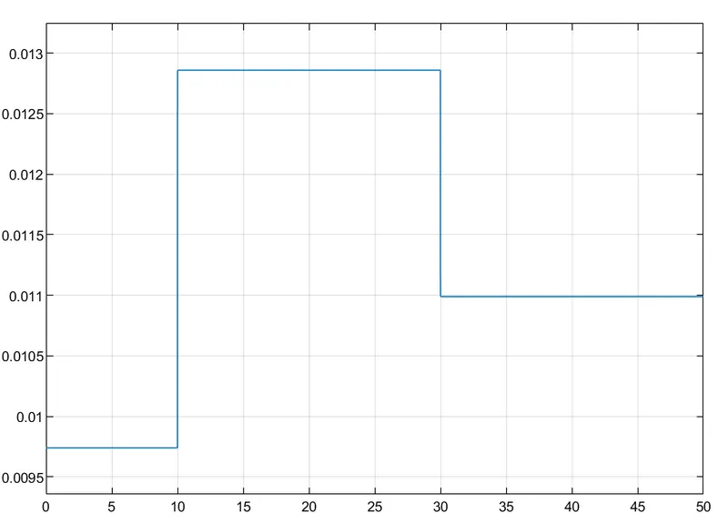
- From the above figure, voltage changes with temperature, using these conditions for fan can be set to ON and OFF
- The fan is ON only when temperature is above 25 degree celsius, from the above graph when voltage is more than 0.011 the fan is ON and when voltage is below 0.011 the fan is OFF
- To switch the fan ON and OFF, a 'Switch Block' is used that routes the signals based on the given conditions
- The centre port of 'Switch Block' is connected to output of 'PS-Simulink Converter' that gives the voltage values. The top port of the 'Switch Block' is connected to a 'Constant Block' of value 1 and bottom port of the 'Switch Block' is connected to another 'Constant Block' of value 0.
- Setting the threshold value of 'Switch Block', Since, the switch is ON only when temperature above 300K so threshold is 0.011. Voltage more than 0.011, the switch gives value '1' as output which means fan will be ON and voltage less than 0.011, the voltage value is '0' and the fan will OFF.
- Switch block connected to 'Scope' to see the output
- From above clearly when the temperature is above 300K the fan is ON and the below temperatures it will be in OFF mode.