Week -2
SIMULINK MODEL OF A DOOR BELL USING SOLENOID BLOCK
We know that magnetism is produced when electric current passes through the wire. If the current is allowed to pass through a wire magnetic field lines are produced. The direction of field lies depends on the direction of current. Just as shown in the figure below, the direction of field lines are always around the wire, when electric current pass through it. The direction of magnetic lines can be determined by using a right hand thumb rule, where thumb gives the direction of current and the direction of folding of other fingers give the direction of magnetic field.
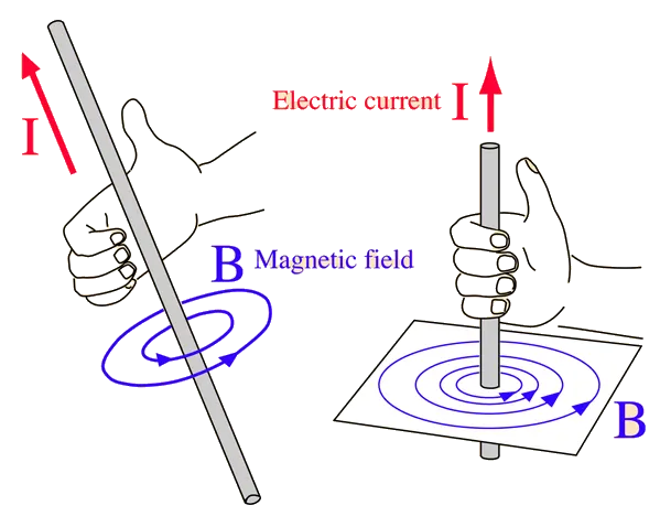
It is always more advantage to have a magnetic field produced with the help of electtric current, as unlike permanent magnet, magnetism exhibited by conducting wires can be stopped. But using a single wire coil does not help to produce enough intensity for practical purpose as large current maybe needed to produce magnetic effect. Hence inorder to have a much more effective magnetic effect produced by current, solenoids are used.
Solenoid are conductive wire wound in a cylindrical shape. The compactness of winding and the number of winding dictates the effectiveness of magnetism produced. By using coiled structure, we can use solenoid for practical purposes.
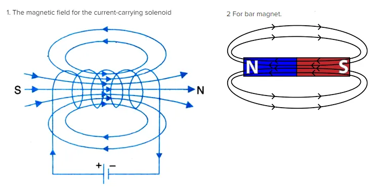
Hence just as a permanent magnet produce magnetic field, solenoid also produce magnetic field lines. The ploarity of magnetic lines depends on the direction of current flow. It is to be noted that rather than not only polarising the coil, the magnetic field also passes through the inside of solenoid moving from south to the north pole. This movement of field lines are utilised in many practical aplication of solenoid.
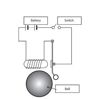
A simple illustration of the ding doll bell can explain how magnetism in solenoid is utilised. In the given figure, when the switch is closed, the electric current passes through the circuit. The current then magnetises the solenoid, due to this the metal contact attached to the clapper gets attracted to the solenoid and exterts a pulling force. The mass attached to the clapper hence move towards the bell striking during this process.Once the switch is open, the magnetism is lost as clapper move back to its original position.
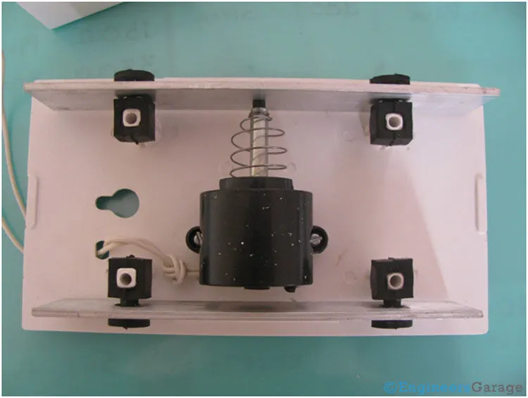
On a practical persepective most of the ding dong bell looks like this. Here a plunger is given inside the solenoid , that is inside a casing (black).Once electric current pass through, the solenoid gets magentised and pulls the plunger into the casing and through to the other side. A striker provided at the end of plunger, strikes against two tuning bars (white), hence producing the sound. It is to be noted that a spring is provided. This is provided to bring back the plunger to its original position once the circuit is open. The value of spring constant, the mass of plunger and the damping constant all determine the velocity of striking the tuning bars.
Hence while modeling a ding dong bell, following components are to be provided
- a dc power supply with a switch that closes while meeting a criteria.
- a solenoid that magnetise when the circuit is closed
- a signal generator that helps to provide criteria for switch closing and opening
Considering these, the ding dong bell can be modelled as
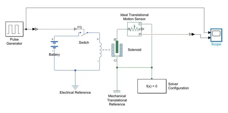
Here
- A pulse generator is used to give the input signal. The input configuration can be given as
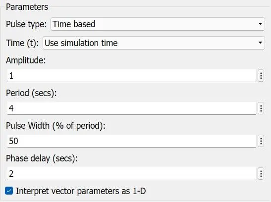
- A switch is provided so that whenver the amplitude becomes greater than the threshold 0, the circuit closes and the solenoid gets energised
- The spring constant value and damping constant value along with the mass of plunger are configured for the solenoid
- The motion of the plunger is mapped ussing an ideal translational motion sensor
- Electrical and mecahnical translational reference are provided along with solver configuration for solving the network.
- Scope is provided for visualising the result
The spring contant and damping coefficent for the model given is
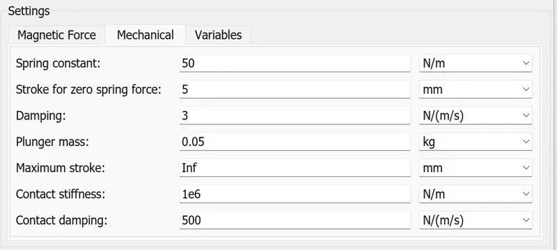
The output of the problem simulated for 20 s is then obtained in scope
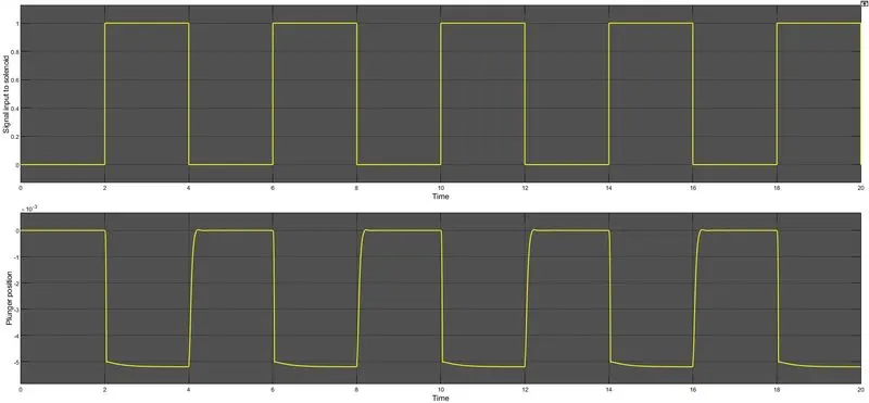
Hence during instances when the circuit gets closed that is at time instances 2 to 4,6 to 8,10 to 12,14 to 16 and from 18 to 20, the plunger motion is obtained in the output, whereas during all other time instants, the plunger is at rest. ie at zero.
google drive for the model
https://drive.google.com/file/d/1YCXbnB2PFnr8XhZ4aUSsjK4ltRO9bJWJ/view?usp=sharing
SIMULINK MODEL FOR THERMISTOR CONTROLLED FAN
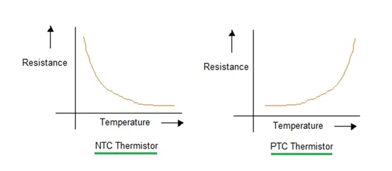
A thermistor is a type of resistor whose resistance changes according to the temperature. Since being sensitive to temperature , they are used in systems involving heat to trigger a circuit. There are mainly two type of thermistor , they are
- NTC thermistor
The Negative Temperature Coefiicient Thermistor is a type of resistor in which the resistance decreases with increase in the temperature
- PTC thermistor
The positive Temperature Coefficient thermistor is a the one in which the resistance increases with increase in temperature.
A comparitive graph of both ae given below
Hence inorder to solve the given problem, we need to address the following
- Build a signal to be provided into the heat source that matches the condition given in the question. ie. 20 degree celcius for 0 to 10 s, 27 degree celcius for 10 to 30 s, 23 degree celcius for 30 to 50 s.
- A condition to switch on the electrical circuit for switching on the circuit , when the necessary voltage condition is met
- A mechanical system of motor for driving the fan connected to the circuit
- A rotational motion sensor to obtain the result by plotting rpm
Hence inorder to build the signal for the problem, we can use the signal builder block, provided, here, the preset graph can be modifies to meet the problem. The signal output obtained is given as
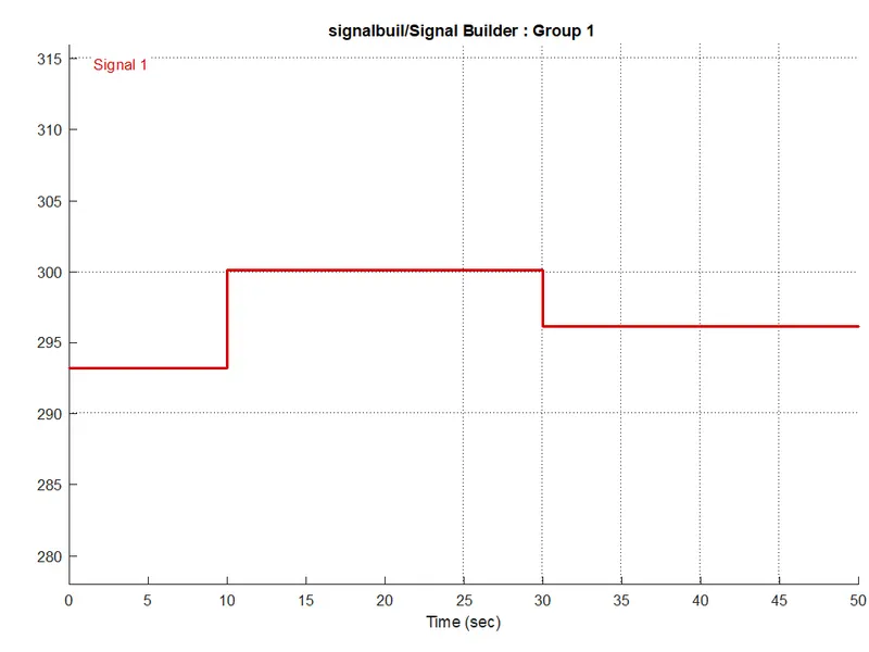
The temperature is marked in kelvin in y axis. Hence it is visible that temperature remains at 293.15 k for 0 to 10, 300.15 k from 10 to 30s and 296.15 K at 30 to 50 s.
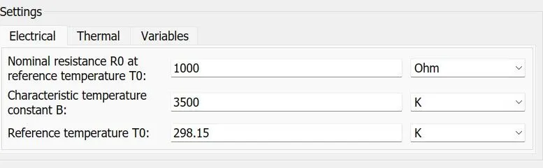
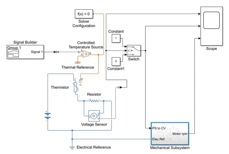
After building the signal, the signal is converted into physical signal to be given into the temperature source, to which the thermistor is connected. Here the temperature limit of 25 degree celcius or 298.15 K is given as the condition in thermistor. This can be given as :
Once the temperature is given, the NTC thermister is then connected to a dc source. A resistor is connected in series connection with the thermistor. The voltmeter connected across the resistor gives the voltage changes that occur in the circuit.
It is to be noted, that before giving in the signal builder, giving a constant signal of 298.15 K as input can help to determine what voltage drop happens across the resistor so that, while giving the switch threshold, this voltage value can be given while build up signal is given as input. The voltage threshold obtained is 0.5703 V across a resistor of 50 ohm connected to a 12 V dc supply.
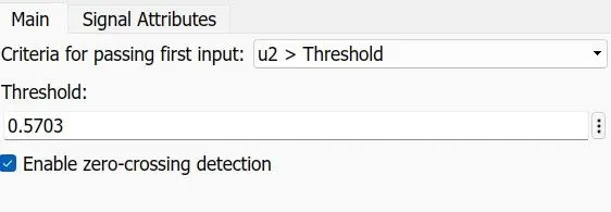
Inorder to trace the time points whe switch is on, a 1 or 0 condition is given. hence the time instances of circuit closed will give value 1, which in turn turn on the dc motor, or else the circuit remains open.
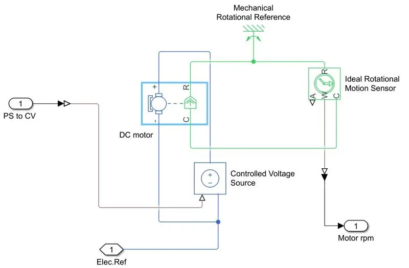
Once the electrical system is complete, the supply is given into a dc motor, the dc motor, runs only when the circuit gets closed, that is when the thermistor temperature crosses, the linit of 298.15 k. From the built up signal it is visible that this temperature range is between 10 and 30 s.
The mechanical system along with a dc motor is given a rotational motion sensor to plot the response of the motor. This motor can be further used for driving the fan. A controlled voltage source is added to drive the motor that obtains the physical signal from the voltmeter.
Electrical reference, thermal refernce as well as ideal rotational reference are provided to the system.
Inorder to plot the motor rpm, a ideal rotational motion sensor is connected, from which motor rpm is connected to the scope.
The entire system can be hence modelled as
The mechanical subsytem can be modelled as
The output scope obtained is
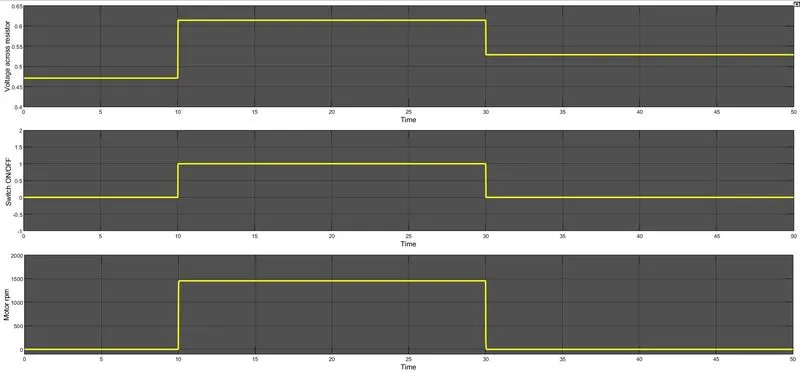
Hence from the above plot, it is visible, that for the time 10 to 30 s, when the temperature is 300.15 k , ie above the threshold value of 298.15 K, the voltage gets peaked across the resistor reaching above the threshold voltage value of 0.5703 corresponding to the the temperature of 298.15 K, which in turn returns a 1 value in switch , thereby connecting the motor circuit and powering it. The oupur rpm of motor, for that time period is obtained using the sensor.
google drive for the model
https://drive.google.com/file/d/1bko_3ciFEB9UliLjiK9LQcjuU5q18BME/view?usp=sharing
REFERENCES