Week -2
AIM:
- To create a model for Door Bell and a Fan using blocks in Simulink.
OBJECTIVE:
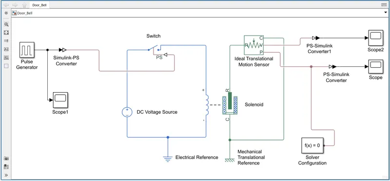
- To model a Door Bell by creating a situation where the switch is closed for 2 seconds and then released. Observe the physical movement of the plunger.
- To model a Fan by using a thermistor to sense the temperature of a heater & turn on or turn off the Fan as per the below conditions:
- Temperature Source:
- 20 °C from 0 to 10 seconds.
- 27 °C from 10 to 30 seconds
- 23 °C from 30 to 50 seconds
- Fan Condition:
- ON if the temperature is above 25 °C.
- OFF Otherwise.
1. MODELLING OF A DOOR BELL:
INTRODUCTION:
- A doorbell is a signaling device typically placed near a door to a building's entrance. When a visitor presses a button the bell rings inside the building, alerting the occupant to the presence of the visitor. Although the first doorbells were mechanical, activated by pulling a cord connected to a bell, modern doorbells are electric, operated by a pushbutton switch.
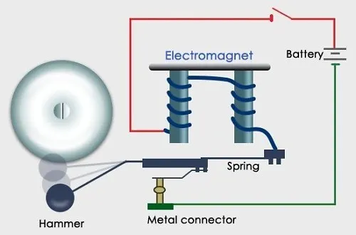
- The heart of a doorbell is an electromagnet. Electromagnets are coils of wire wrapped around a small piece of magnetic metal. When electricity passes through the wire, it creates a magnetic field around the wire.
- When you press a doorbell button, you complete an electrical circuit that allows household electricity to flow through the doorbell's internal electromagnet. The magnetic field generated by the electromagnet is then used to power a mechanism that creates the doorbell sound.
- Doorbells are low-voltage devices. This means they require relatively little energy to operate. An important part of a doorbell mechanism is the transformer. The transformer converts regular 120-volt household current to the lower voltage (usually somewhere between 6-16 volts) required by the doorbell.
- Most doorbells have what's called a "push-to-make" switch outside your door, like the one in our top photo. When you prod the button, your finger pushes two electric contacts together to complete ("make") the circuit; when you release the pressure, a spring moves the button back out again so the circuit is interrupted. Like my own primitive doorbell, the circuit itself contains only two basic elements: a battery and something that makes a noise. The "something" is often an electric bell: a little metal bell and a clapper (hammer) powered by an electromagnet. When someone presses the button, the electromagnet is activated and pulls on the clapper, which strikes the bell. But here's the clever bit: the clapper is actually also part of the circuit. When it flips out to strike the bell, it breaks the circuit at the same time, cutting the power to the electromagnet. A spring attached to the clapper pulls it back to its original position, whereupon it completes the circuit, energizes the electromagnet, and rings the bell once more. This goes on for as long as you keep the button pressed. Or until the batteries run out.
MODELLING USING SIMULINK:
MODEL:
BLOCKS USED:
1. Pulse Generator:
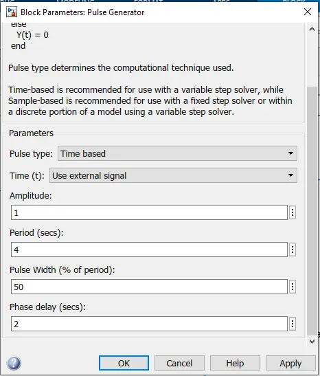
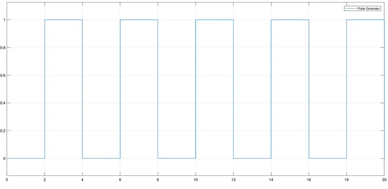
- Used to generate the desired pulse. In the above assignment we require a pulse for 2 seconds. That is for 2 seconds we need the switch to be closed so that current can flow to the solenoid.
2. SWITCH:
- The block represents a switch controlled by an external physical signal. If the external physical signal PS is greater than the threshold, then the switch is closed, otherwise the switch is open.
3. DC VOLTAGE SOURCE:
- The ideal voltage source maintains a constant voltage across its output terminals, independent of the current flowing through the source. The output voltage is defined by the Constant voltage parameter, and can be any real value.
4. SOLENOID:
- This block implements the electrical and mechanical characteristics of a solenoid. Parameterization is in terms of two points [X1,F1] and [X2,F2] on its force-stroke curve for a 100 percent duty cycle at Rated voltage Vdc and Rated current Idc where X2>X1>0 are stroke values and F1>F2>0 are corresponding forces. The plunger fully in (i.e. air gap closed) corresponds to X=0, and pull-in force is assumed to decrease quadratically with the magnitude of X. To ensure the force remains finite, the following condition should hold: X2/X1>sqrt(F1/F2).
- The plunger Maximum stroke is implemented as a hard stop, the dynamics of which are set by the Contact stiffness and Contact damping parameters. The same parameters are used to model the contact dynamics when the plunger pulls fully in. The Spring constant parameter is used to implement a spring force that pulls the plunger out, and can be set to zero.
5. IDEAL TRANSLATIONAL MOTION SENSOR:
- This block measures velocity or displacement in a mechanical translational network. The sensor is ideal since it does not account for inertia, friction, delays, energy consumption, and so on.
- The physical signal ports V and P report the velocity and position, respectively, of port R relative to port C. The measured velocity is positive when the velocity at port R is greater than the velocity at port C.
6. SOLVER CONFIGURATION:
- Each physical network represented by a connected Simscape block diagram requires solver settings information for simulation. The Solver Configuration block specifies the solver parameters that your model needs before you can begin simulation.
- Each topologically distinct Simscape block diagram requires exactly one Solver Configuration block to be connected to it.
7. SIMULINK-PS CONVERTER:
- Converts the Simulink input signal to a Physical Signal.
- The unit expression in 'Input signal unit' parameter is associated with the Simulink input signal and determines the unit assigned to the Physical Signal.
8. PS-SIMULINK CONVERTER:
- Converts the input Physical Signal to a Simulink output signal.
- The unit expression in 'Output signal unit' parameter must match or be commensurate with the unit of the Physical Signal and determines the conversion from the Physical Signal to the Simulink output signal.
9. ELECTRICAL REFERENCE:
- Electrical reference port. A model must contain at least one electrical reference port (electrical ground).
- The Electrical Reference block represents an electrical ground. Electrical conserving ports of all the blocks that are directly connected to ground must be connected to an Electrical Reference block.
10. MECHANICAL TRANSLATIONAL REFERENCE:
- The Mechanical Translational Reference block represents a reference point, or frame, for all mechanical translational ports. All translational ports that are rigidly clamped to the frame (ground) must be connected to a Mechanical Translational Reference block.
11. SCOPE:
- Use to display the results in a graphical manner.
- Use to display the Time domain signals.
RESULT:
1. GENERATED PULSE:
2. POSITION OF THE PLUNGER:
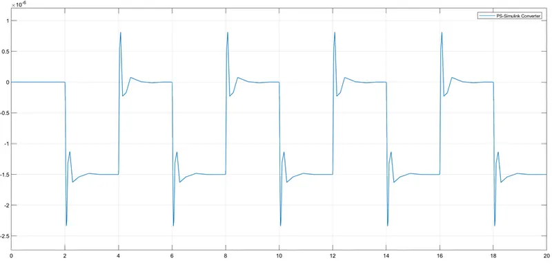
3. VELOCITY OF THE PLUNGER:
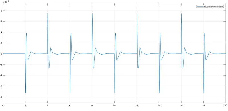
2. MODELLING OF A FAN USING A THERMISTOR:
- To model a Fan by using a thermistor to sense the temperature of a heater & turn on or turn off the Fan as per the below conditions:
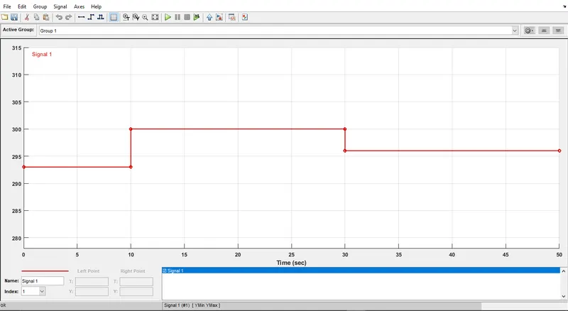
- Temperature Source:
- 20 °C from 0 to 10 seconds.
- 27 °C from 10 to 30 seconds
- 23 °C from 30 to 50 seconds
- Fan Condition:
- ON if the temperature is above 25 °C.
- OFF Otherwise.
MODELLING USING SIMULINK:
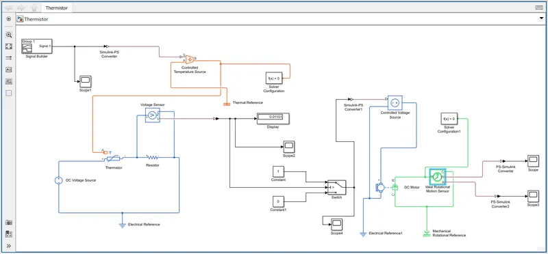
BLOCKS USED:
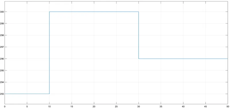
1. SIGNAL BUILDER:
- To create a Signal as per the required condition.
2. CONTROLLED TEMPERATURE SOURCE:
- This block represents an ideal energy source in a thermal network that can maintain a controlled temperature difference regardless of the heat flow rate.
- The temperature difference is set by the physical signal port S. A positive temperature difference causes the temperature at port B to be greater than the temperature at port A.
3. THERMISTOR:
-
This block represents an NTC thermistor using the B-parameter equation. The resistance at temperature T is given by R(T) = R0*exp(B*(1/T-1/T0)) where R0 is the Nominal resistance at the reference temperature T0, and B is the Characteristic temperature constant. The temperature T of the thermistor is governed by the equation m*c*dT/dt = Q where Q is the net heat flow into port A, m is the mass and c is the lumped specific heat capacity. The thermal mass m*c is calculated from the Thermal time constant t_c and the Dissipation factor K_d using the equation m*c = K_d*t_c.
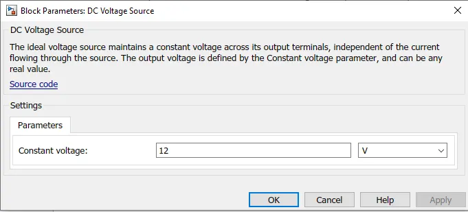
4. DC VOLTAGE SOURCE:
-
The ideal voltage source maintains a constant voltage across its output terminals, independent of the current flowing through the source. The output voltage is defined by the Constant voltage parameter, and can be any real value.
5. RESISTOR:
- The voltage-current (V-I) relationship for a linear resistor is V=I*R, where R is the constant resistance in ohms.
- The positive and negative terminals of the resistor are denoted by the + and - signs respectively. By convention, the voltage across the resistor is given by V(+)-V(-), and the sign of the current is positive when flowing through the device from the positive to the negative terminal. This convention ensures that the power absorbed by a resistor is always positive.
6. VOLTAGE SENSOR:
- The block represents an ideal voltage sensor, that is, a device that converts voltage measured between any electrical connections into a physical signal proportional to the voltage.
- Connections + and - are conserving electrical ports through which the sensor is connected to the circuit. Connection V is a physical signal port that outputs voltage value.
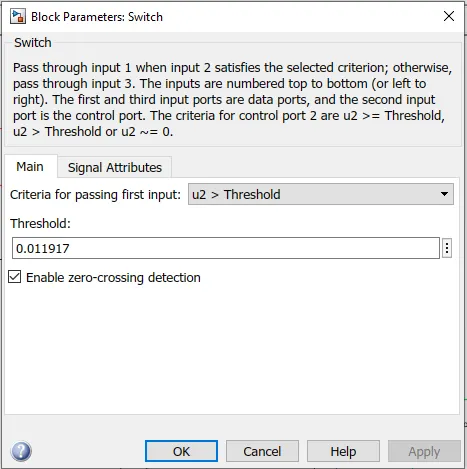
7. SWITCH:
-
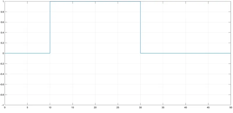
To pass through input 1 when input 2 satisfies the selected criterion; otherwise, pass through input 3. The inputs are numbered top to bottom (or left to right). The first and third input ports are data ports, and the second input port is the control port. The criteria for control port 2 are u2 >= Threshold, u2 > Threshold or u2 ~= 0.
8. SOLVER CONFIGURATION:
- Each physical network represented by a connected Simscape block diagram requires solver settings information for simulation. The Solver Configuration block specifies the solver parameters that your model needs before you can begin simulation.
- Each topologically distinct Simscape block diagram requires exactly one Solver Configuration block to be connected to it.
9. DC MOTOR:
- This block represents the electrical and torque characteristics of a DC motor.
- The block assumes that no electromagnetic energy is lost, and hence the back-emf and torque constants have the same numerical value when in SI units. Motor parameters can either be specified directly, or derived from no-load speed and stall torque. If no information is available on armature inductance, this parameter can be set to some small non-zero value.
- When a positive current flows from the electrical + to - ports, a positive torque acts from the mechanical C to R ports. Motor torque direction can be changed by altering the sign of the back-emf or torque constants.
10. CONTROLLED VOLTAGE SOURCE:
-
The block represents an ideal voltage source that is powerful enough to maintain the specified voltage at its output regardless of the current passing through it. The output voltage is V = Vs, where Vs is the numerical value presented at the physical signal port.
11. IDEAL ROTATIONAL MOTION SENSOR:
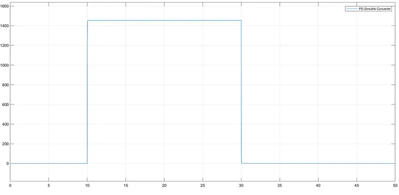
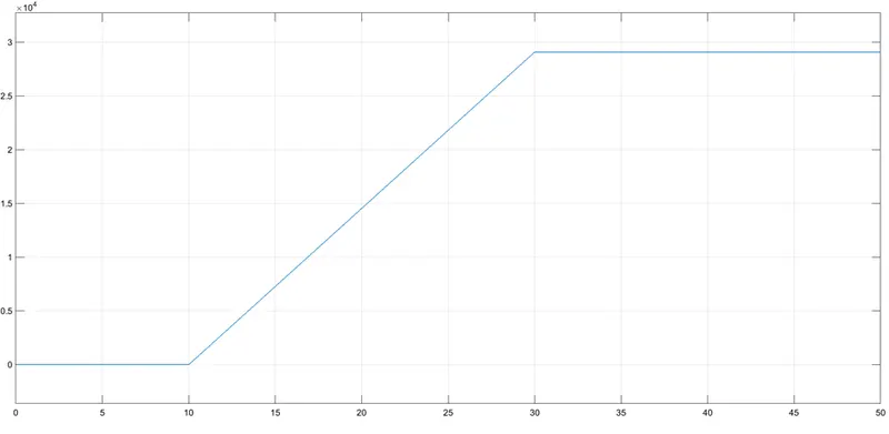
- This block measures angular velocity or angle in a mechanical rotational network. The sensor is ideal since it does not account for inertia, friction, delays, energy consumption, and so on.
- The physical signal ports W and A report the angular velocity and angle, respectively, of port R relative to port C. The measured angular velocity is positive when the angular velocity at port R is greater than the angular velocity at port C.
12. SIMULINK-PS CONVERTER:
- Converts the Simulink input signal to a Physical Signal.
- The unit expression in 'Input signal unit' parameter is associated with the Simulink input signal and determines the unit assigned to the Physical Signal.
13. PS-SIMULINK CONVERTER:
- Converts the input Physical Signal to a Simulink output signal.
- The unit expression in 'Output signal unit' parameter must match or be commensurate with the unit of the Physical Signal and determines the conversion from the Physical Signal to the Simulink output signal.
14. ELECTRICAL REFERENCE:
- Electrical reference port. A model must contain at least one electrical reference port (electrical ground).
- The Electrical Reference block represents an electrical ground. Electrical conserving ports of all the blocks that are directly connected to ground must be connected to an Electrical Reference block.
15. MECHANICAL ROTATIONAL REFERENCE:
-
This block represents a mechanical rotational reference point, that is, a frame or a ground. Use it to connect mechanical rotational ports that are rigidly affixed to the frame (ground).
16. SCOPE:
- Use to display the results in a graphical manner.
- Use to display the Time domain signals.
17. DISPLAY:
-
Display input values. If the incoming signal is of type string, the 'Numeric display format' parameter selection does not affect the display of the string.
18. CONSTANT:
-
Output the constant specified by the 'Constant value' parameter. If 'Constant value' is a vector and 'Interpret vector parameters as 1-D' is on, treat the constant value as a 1-D array. Otherwise, output a matrix with the same dimensions as the constant value.
RESULTS:
1. SIGNAL BUILDER:
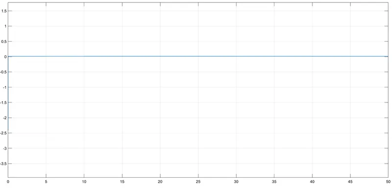
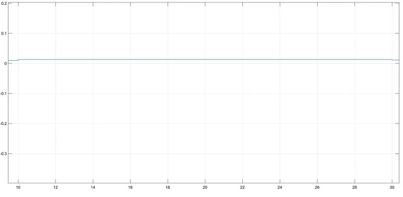
2. TIME VS VOLTAGE:
3. RESULT FROM SWITCH:
4. ANGULAR VELOCITY:
5. ANGLE:
CONCLUSION:
- From the above assignment we learnt how to model a Door bell and a Fan using a Thermistor.