Week -2
Door Bell Challenge
Aim:-
The aim of this project is to simulate the model of a door bell which is closed for 2 sec and then released
Procedure:-
In this model we will use the following elements
- Pulse Generator (to generate the required signal wave)
- Switch (to operate the bell according to signal)
- Battery (to provide power to the circuit)
- Solenoid (to convert electrical energy to mechanical energy)
- Ideal translational motion sensor (to sense the movement of the metal arm)
- Scope (to display the signals)
- PS to Simulink convertor (to convert physical signal to simulink signal)
- Simulink to PS convertor (to convert simulink signal to physical signal)
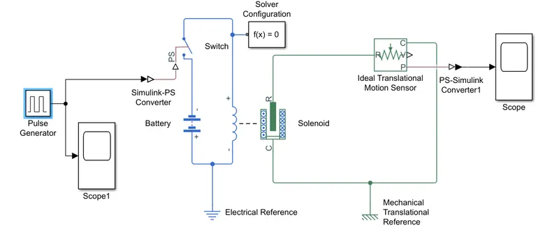
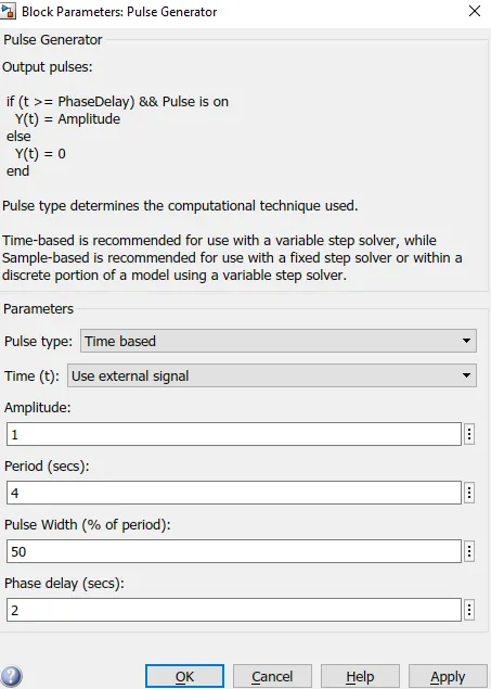
By using the pulse generator we generate the required signal (with delay of 2 secs), with the help of which we can operate the switch and send the signal to solenoid and then the ideal translational motion sensor senses the motion of the metal arm and give the output signal on the scope
SIMULINK MODEL for DOOR BELL
Configration of pulse generator
CONCLUSION:-
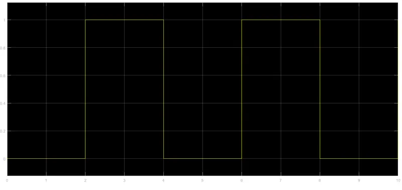
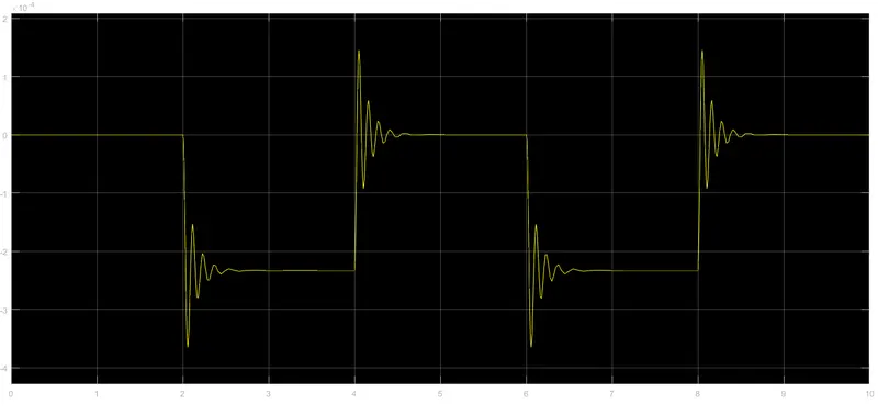
As the result of the input wave with delay of 2 sec(as the switch is off for 2 secs) we can see the movement of the wave after every 2 secs in the output signal wave
Input Signal
Output For Translational sensor (for metal arm)
Thermistor Challenge
Aim:-
The aim of this project is to simulate the model of a Automatic fan heater using the Thermistor which sense the temperature and work accordingly
Procedure:-
In this model we will use the following elements
- Signal Builder (to generate the required signal wave)
- Temperature controlled source(to provide a temperature physical output based on the condition given to port s
- Thermistor ( to show the relation between temperature and resistance)
- Voltage sensor ( to measure the potential difference between any 2 points)
- Resistor (to provide the opposing nature to the current in the circuit)
- Switch (to operate the fan according to signal)
- Battery (to provide power to the circuit)
- Controlled voltage source (to give the constant voltage to the local circuit)
- DC Motor ( to take electrical input and give rotational mechanical outout)
- Ideal rotational motion sensor (to sense the movement of the fan motor)
- Scope (to display the signals)
- PS to Simulink convertor (to convert physical signal to simulink signal)
- Simulink to PS convertor (to convert simulink signal to physical signal)
- Electrical and Thermal references ( to provide the initial condition to the thermal and electrical block for solver
By using the Signal Builder we can generate the signal according to our requirements
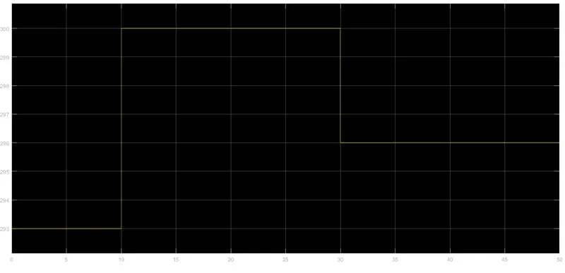
0 to 10 sec temperature is 20◦C
10 to 30 sec temperature is 27◦C
30 to 50 sec temperature is 23◦C
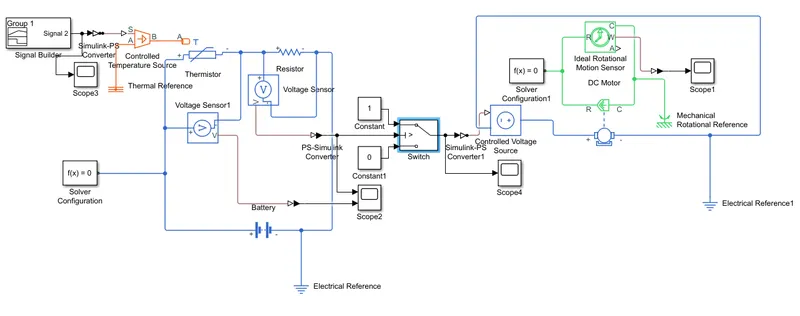
Now the signal generated is given to thermistor through the temperature controlled source, which is then connected to the resistor and a 12volt battery, and further it is connected to a conditional switch which takes input for the thermistor and if the value is greater than threshold than the switch is turned on of otherwise it is off. The switch is further connected to the fan motor and a constant voltage supply which id thereafter connected to rotational motion sensor to sense the motion of the fan and give the output as signal in the scope.
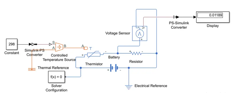
The threshold is calculated by the same model with some modifications as we require, our fan should be turned on if the temperature is more than 25◦C, so we give the thermistor a constant supply of 298K (K=273+C) and obtain the threshold voltage in the diplay (which is 0.01189).
SIMULINK MODEL FOR AUTOMATIC FAN CONTROLLER
Simulink model to calculate the value of threshold value for fan to operate
Conclusion :-
As the result of the input signal
0 to 10 sec temperature is 20◦C
10 to 30 sec temperature is 27◦C
30 to 50 sec temperature is 23◦C
we were able to operate the fan for condition
fan on if tempareture in >25◦C
else off
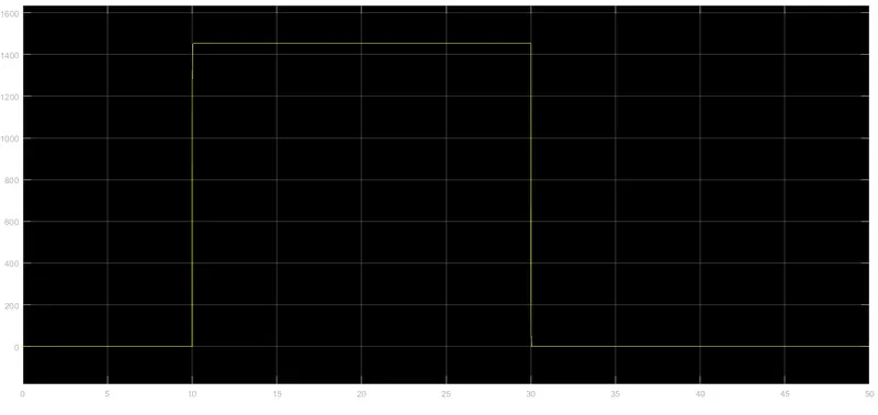
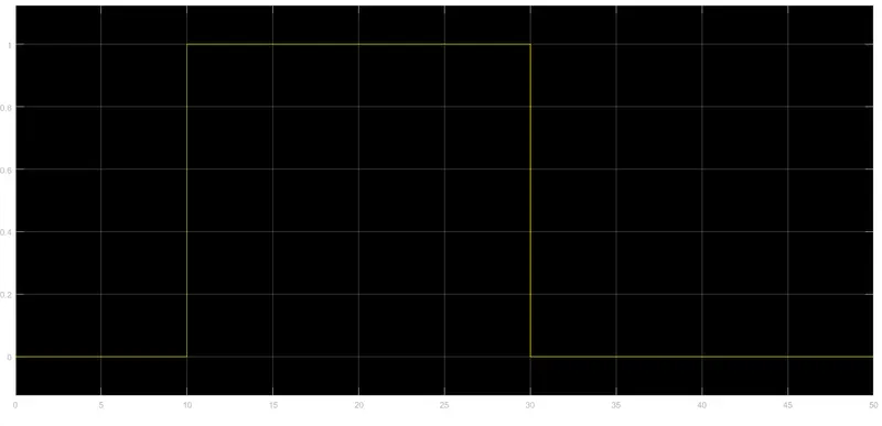
we can also see in the scope that the rotational motion sensor has given output during the time when tempareture was 27◦C (i.e. >25◦C)
Input Signal:-
Switch Output
Rotational sensor Output