Week -2
Aim :1. Make a Simulink model of Doorbell using solenoid block with the following details:
In the above arrangement, when the switch is closed the electromagnet receives electrical power from the battery and pulls the metal arm to hit the bell producing sound.
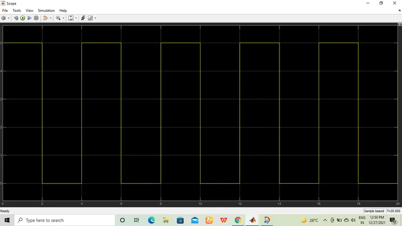
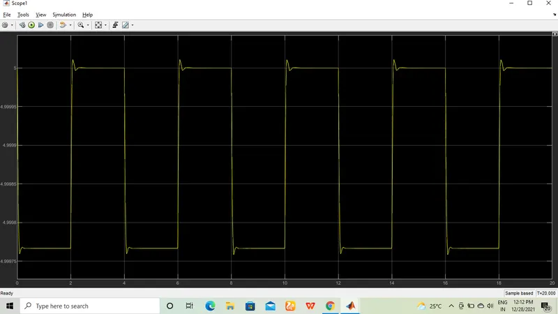
Create a situation where the switch is closed for 2 seconds and then released. Observe the physical movement of the plunger.
Assume remaining parameters.
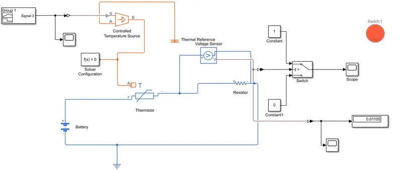
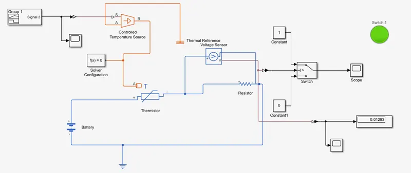
2. Use a thermistor to sense the temperature of a heater & turn on or turn off the fan as per the below conditions:
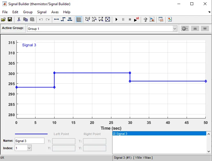
Temperature source: 20 °C from 0 to 10 seconds, 27 °C from 10 to 30 seconds, 23 °C from 30 to 50 seconds
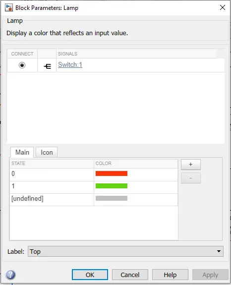
Fan conditions: ON if the temperature above 25 °C, OFF otherwise
1. Simulink model for the dooebell.
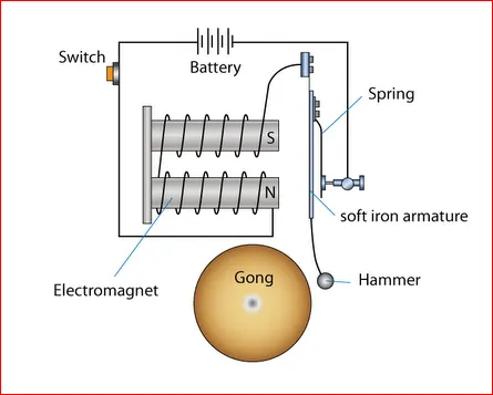
Theory
The most important part of a door bell is its magnetic motor. The magnetic motor constitutes a conventional electromagnet. We know that an electromagnet is an arrangement in which a coil of wire is wrapped around magnetic material which produces magnetic field when electricity is passed through the coil. The greater the coiling of the wire, the higher the amplification of magnetic field. This magnetic field produces a substantial effect on any magnetic substance when brought in the vicinity of its magnetic field. This means that when an iron object is placed in this magnetic field, it will be attracted towards the magnetic field due to polar orientation generated by the electromagnetism.
When the door bell button is pressed, an electrical circuit is closed, which leads to the flowing of electric current through the electromagnet.
This current passes through a transformer which turns the 120 V current into usable 10 V current. The current then passes through the electromagnetic wire winding. A magnetic field is generated as a result, which is used to drive a sound making mechanism. Different types of sound making mechanisms are used to generate different sorts of noises.
SIMULINK MODEL
Procedure
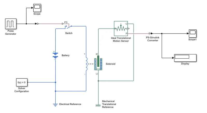
- A pulse generator input signal is used to provide the input.
- Input signal is connected to the switch via a simulink-ps converter block.
- There are 3 ports to the switch one is already connected to the input signal and the other two are connected to a Battery and the Solenoid and also an electrical reference block is used.
- One of the ports of the solenoid is connected to an ideal transtional motion sensor and the other is connected to a mechanical translational reference.
- The sensor is then connected to a scope via a ps-simulink converter to observe the output.
- Initial position for the sensor is given as 5.
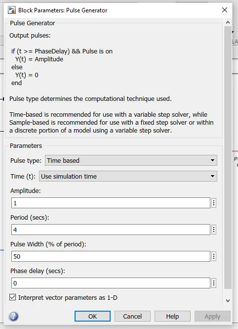
INPUT PARAMETERS
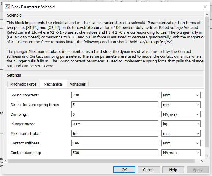
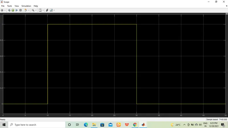
Output Obtained
2. Use a thermistor to sense the temperature of a heater & turn on or turn off the fan
Theory
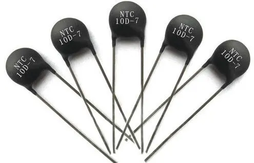
Thermistor : A thermistor is a thermally sensitive resistor that exhibits a precise and predictable change in resistance proportional to small changes in body temperature. How much its resistance will change is dependent upon its unique composition.
Michael Faraday; an English scientist, first discovered the concept of thermistors in 1833 while reporting on the semiconductor behavior of silver sulfide. Through his research, he noticed that the silver sulfides resistance decreased as the temperature increased. This discovery would later lead to the commercial production of thermistors in the 1930’s when Samuel Ruben invented the first commercial thermistor.
Types of Thermistors
There are two types of thermistors.
- NTC or Negative Temperature Coefficient thermistors.
- PTC or Positive Temperature Coefficient thermistors.
The difference is that NTC thermistors exhibit a DECREASE in resistance as body temperature increases, while PTC thermistors exhibit an INCREASE in resistance as body temperature increases.
Signal Parameters
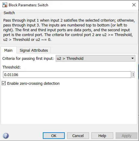
Input Signal
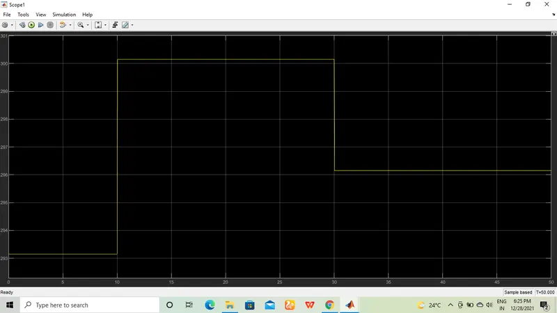
Output Obtained