Week -2
Q1: Doorbell Simulation
In the model shown below we have used the following blocks: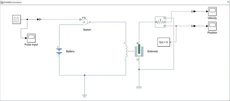
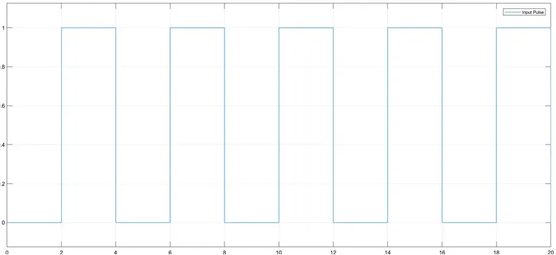
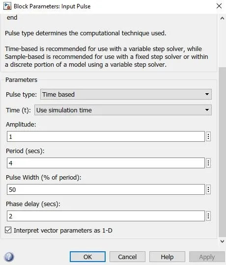
- Pulse Generator: To generate a pulse of duration 4 seconds with a 50% duty cycle and a delay of 2 seconds(optional)
- Battery: 12V Battery as electrical input to the solenoid block.
- Switch: A sim-scape switch to give input to solenoid only in the case of the high pulse from the pulse generator
- Solenoid: A component used to convert an electrical input to mechanical output in the form of plunger motion. Here the plunger moves from R to C.
- Ideal Translational Motion Sensor: It senses the translational motion of the plunger ie. any movement of the plunger.
- References: Electrical and Mechanical(Translational): To provide a reference or appropriate ground to the part of the model.
The results of the simulation are obtained as below:
1) Pulse Input that was given is shown in the plot below-
The parameters of the pulse generator block were edited as:
2) Plunger position- This position of the plunger follows the input pulses. Hence we can conclude that the plunger operates for 2 seconds and then is in the off position or released.
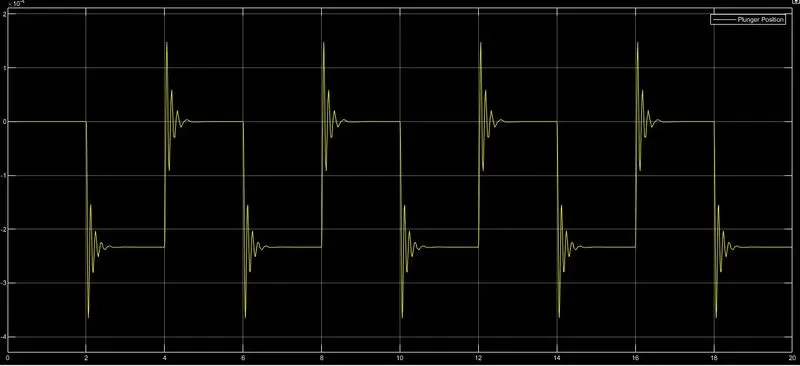
3) Plunger Velocity- The velocity of this translational velocity sensor helps to plot the velocity of the plunger. We can see that in the duration of 10 seconds, the plunger moves 4 times at the rate of once per two seconds.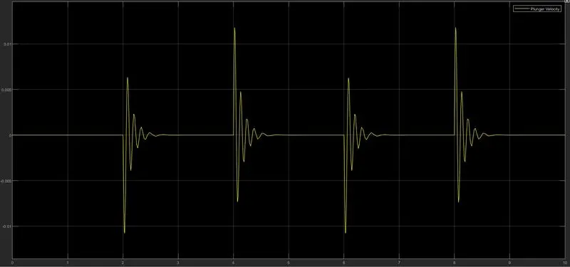
Q2: Operation of a fan based on temperature variation using a thermistor.
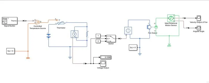
The model shown above uses the following blocks:
- Signal builder- Used to create a signal sequence according to the given statement that related temperature (in Kelvin) with the time in seconds.
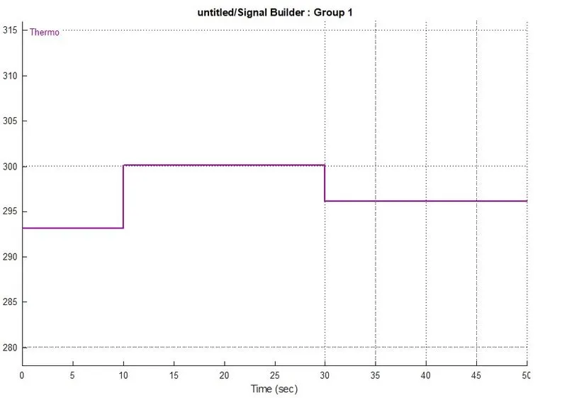
- Controlled temperature source: It uses the physical signal source(S) from the signal builder to give the physical thermal output from the port B to the port A of the thermistor.
- Thermistor: It is used to convert the normal resistance to a temperature dependent resistance such that with varying temperature, the resistance varies and hence the voltage output to the DC Motor varies.
- Voltage sensor: It is used to sense the voltage across the thermistor-resistance setup and hence gives a value for threshold.
- Switch: Used for switching the DC Motor on and off according to the condition of threshold voltage. If V>threshold, the switch is in the ON position and the DC Motor(Fan) activates and is OFF otherwise.
- Controlled Voltage source: The supply to the DC Motor controlled by the signal if passed from the switch.
- DC motor: Represents the Fan that we are modelling. Has an electrical and rotating mechanical part.
- Ideal Rotational Motion Sensor: It senses the rotation of the DC motor and records the velocity and angular output of the fan.
- References: Electrical, thermal, rotational mechanical: acts as the reference or the grounding for the physical system.
Results of the simulation were:
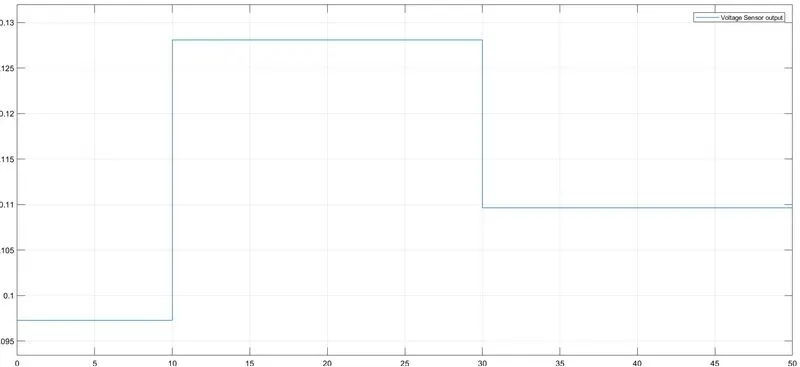
- The Voltage sensor result- Follows the plot of the signal builder signal that was developed based on the temperature.
From here we can note the time at which the voltage when the temperature goes beyond 25 degrees and then use this voltage to set the threshold in the switch block parameters.
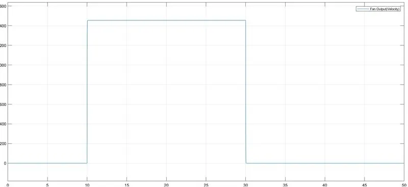
2. Fan Velocity Plot: This plot shows that the DC Motor only gets activated when the temperature goes above 25 degree ie. it gets switched ON when the temperature is 27 degrees from 10 to 30 seconds. It goes up to a speed of over 1400rpm when in operation.
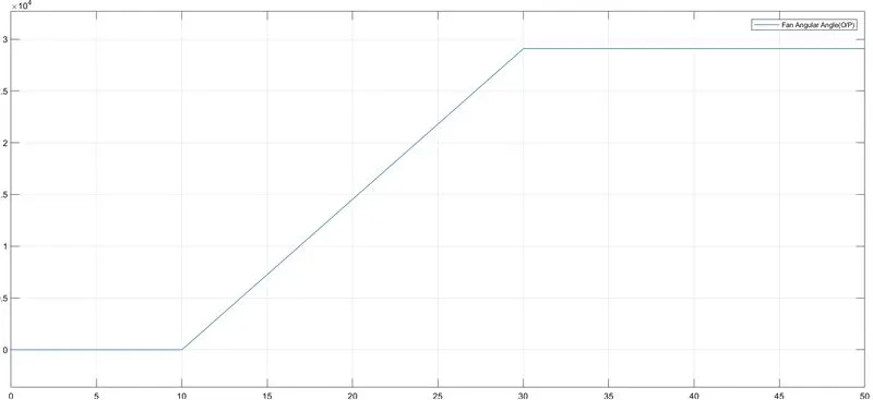
3. Fan Angle: This plot shows the angle of the rotor and follows the fact that the DC Motor is operating only during the period between 10 and 30 seconds.