Week -2
1. Simulink model of Doorbell using solenoid block
AIM & OBJECTIVE -
To make a Simulink model of doorbell using solenoid block and Observe the physical movement of the plunger for a situation where the switch is closed for 2 seconds and then released.
THEORY-
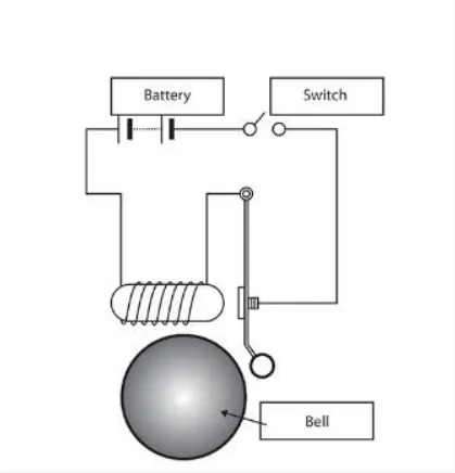
The above figure shows a Block diagram of a electric doorbell. when we observe the figure we can find components like solenoid, plunger, switch and battery.
solenoid- it has a spring shaped coil and plunger which is movable and when the coil is supplied the power there is a magnetic field that is created across the coil and the plunger is made of metal so the plunger moves. it working is similar to a dc motor where movement is rotational and here plunger movement is linear.
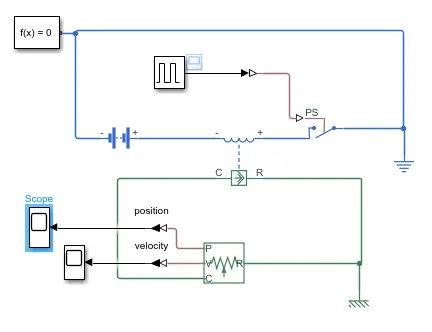
To implement the above doorbell in Simulink we need the following blocks
Battery- for energising the coil. A typical doorbell has battery voltage ranges from 8V to 24V and 16V is more often used in this we used a 16V battery. [1]
Switch- switch is here to ring the doorbell when the switch is on the coil is energised and the solenoid moves the plunger such that the bell rings.
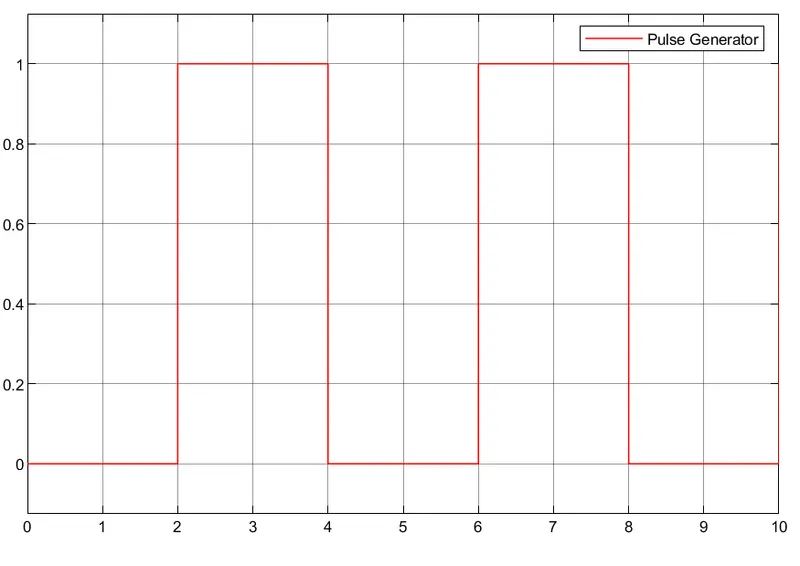
Pulse generator- according to our problem we need to on switch for every 2 seconds so a pulse generator is used to create a waveform of time period 4 seconds where the pulse is high(switch is on) for 2 seconds (half of the time) and pulse is low(off) for the remaining half of time period.
Ideal translational motion sensor- it is used to sense the motion of the plunger and it also outputs the velocity of the movement of the plunger.
Simulink circuit diagram-
Input pulse which is given to switch
output plots-
firstly the battery supply voltage is kept at 16V and the pulse generator is given a 2-second delay shown in the figure above such that there is an on(high pulse) in between 2-4 seconds and we expect the plunger to move and its position can be tracked in the graph below
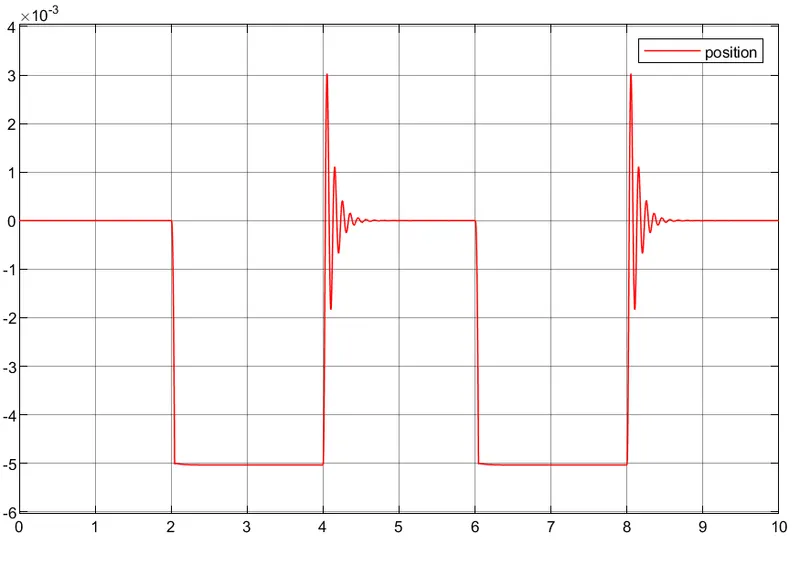
here we can observe when the switch is on plunger position is changed and the bell is ringed after the switch is off we can see some amount of oscillations in the position of the plunger which takes some time to settle to its original position this is due to damping of spring we need to change the spring damping and spring constant such that the transition is smoother
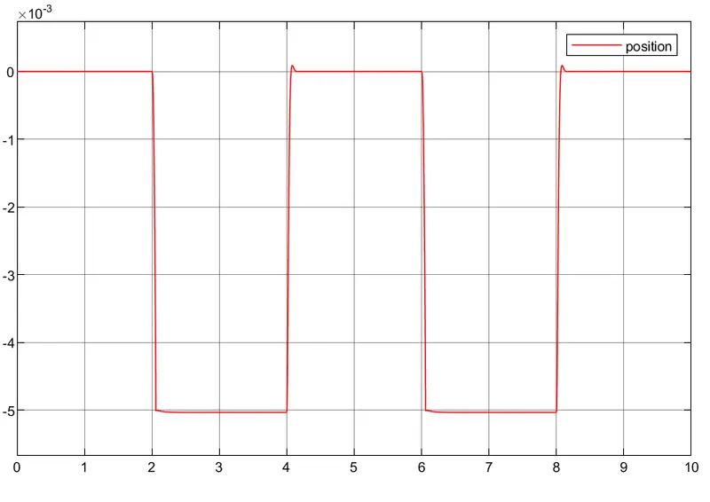
The above figure shows the position of the plunger after changing the damping value from 1 to 5 N/(m/s).
we can see the velocity of the plunger movement before and after changing the damping value in the below figure
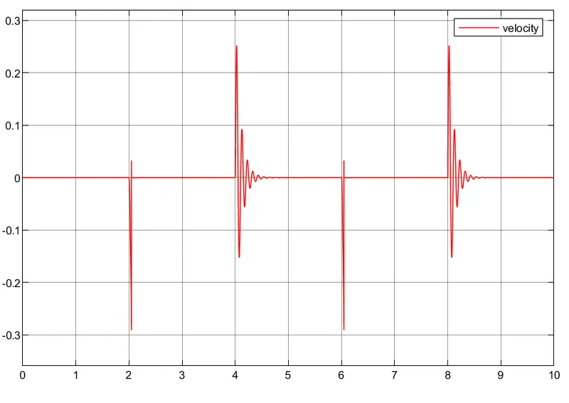
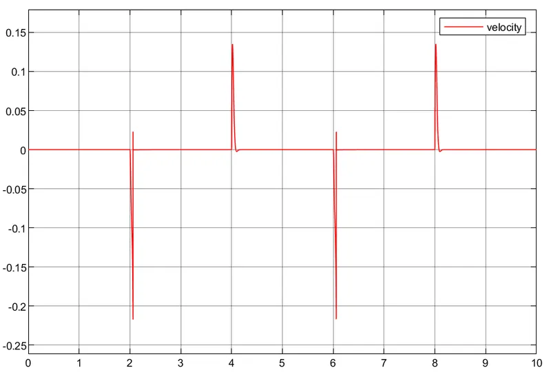
(before) (after)
2. Simulink model to sense the temperature of a heater & turn on or turn off the fan using a thermister
AIM & OBJECTIVE-
To build a model which able to sense the temperature using thermistor and further according to given below condition the fan supply is on or off.
condition- when the temperature is above 25 degrees celsius the fan should turn on
Theory-
Thermistor- It is a resistor that is very sensitive to thermal changes i.e the resistance changes when there is a change in temperature. So, for our application, this device is a better one since we need to detect the change in temperature according to that the fan is on or off. they are classified into two types NTC(negative temperature coefficient) thermistor and PTC(positive temperature coefficient) thermistor. NTC is used as inrush current limiters and temperature sensors and PTC are used as self-resetting overcurrent protectors, for our application we need a temperature sensor so an NTC thermistor is used.
it follows the below equation
`R(T) = Ro + exp(B+(1/T-1/(To)))`
and the values of R0 = 1000 ohm, To = 298.15k, and B = 3500K.
Simulink connection diagram
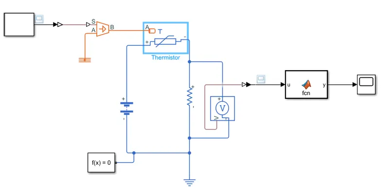
To implement the above logic to sense the temperature using thermistor and give the switching signals to fan on or off is done by using below blocks
Stair generator- here the input change in temperature according to time is implemented using a staircase generator. A staircase generator generates the signal that we want with step rise or fall according to the step value by specifying at which time the value should be changed. for our problem we need to maintain 20 °C (273+20=293K) from 0 to 10 seconds, 27 °C(300K) from 10 to 30 seconds, 23 °C (296K) from 30 to 50 seconds. so the stair case generator has two parameters we can give inside it one amplitude which is given as [293,300,296] here the temperature in degree is converted into kelvin and given and in time parameter we need to input timestamps where our signal need to change i.e, [0,10,30] seconds.
controlled temperature source- the signal is given to a controlled temperature source where it outputs the temperature according to the value given to it by signal.
Battery- To provide power 10 V dc Battery source is used.
Thermistor- it behaves as NTC thermistor
voltage sensor- it senses the voltage across the resistor
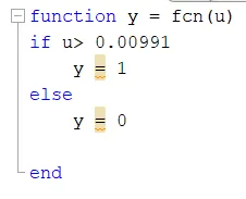
Matlab Function- here the logic when the temperature is above 25 degrees celsius the fan on (output pulse 1) or off(output pulse 0) is implemented using Matlab code shown below here the value of voltage drop across the resistor is used to implement logic and when it is calculated for 25-degree celsius the voltage drop across the resistor is 0.00991V and code is shown in the figure below
plots
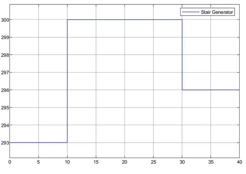
the above figure is the input temperature change given according to time.
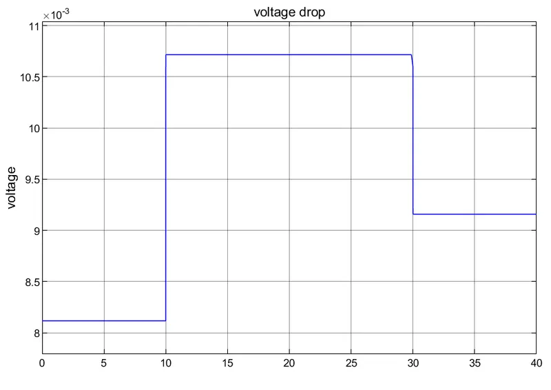
the voltage drop across the resistor for different temperatures
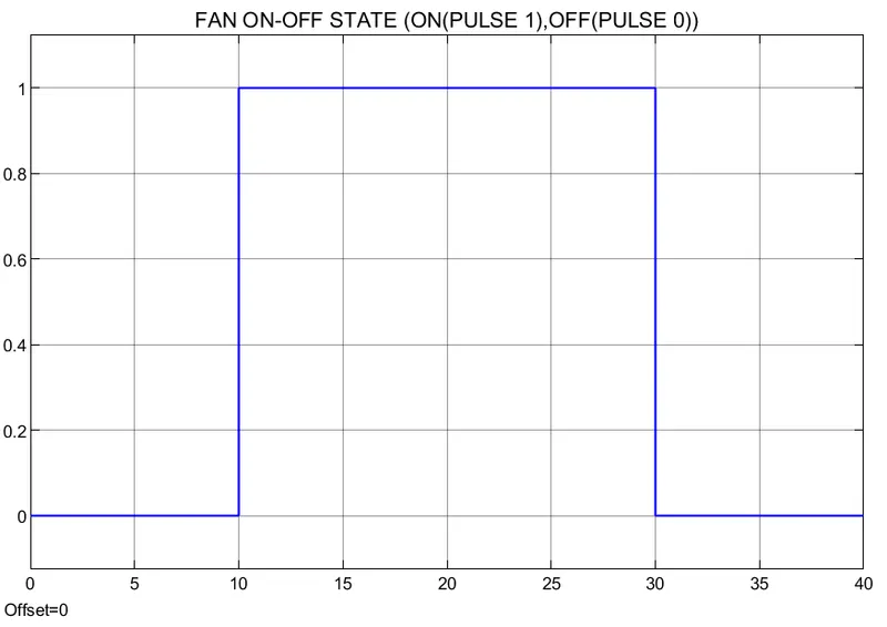
Fan on or off state
conclusion- we can observe the above graph where when the temperature is 20 degrees celsius the fan is off and when the temperature is 27 degrees > 25 degrees the fan switch is on and when again temperature falls below 25 degrees i.e, 23 degrees the fan is off.