Week -2
AIM:
- To make a Simulink model of Doorbell using solenoid block.
- To use a thermistor to sense the temperature of a heater & turn on or turn off the fan.
OBJECTIVE:
- To create a situation where the switch is closed for 2 seconds and then released. Observe the physical movement of the plunger.
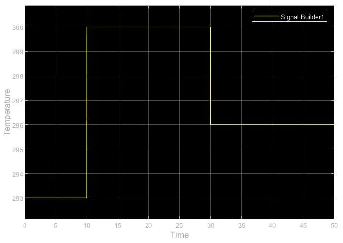
- To sense the temperature of a heater by using some conditions. Temperature source: 20 °C from O to 10 seconds, 27 °C from 10 to 30 seconds, 23 °C from 30 to 50 seconds.Fan conditions: ON if the temperature is above 25 °C, OFF otherwise.
Blocks used to create the Doorbell Simulink Model:
-
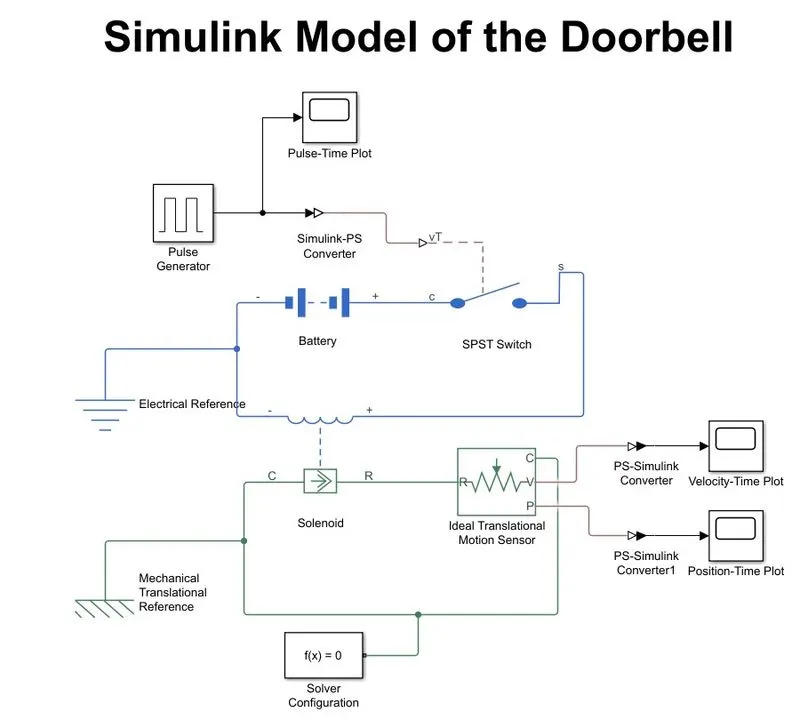
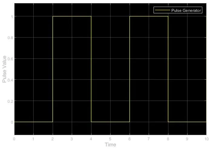
Pulse Generator - Generate pulse to make the switch to on state. Parameters configured are pulse type is time-based, selected as use simulation time, amplitude = 1, Period = 4, Pulse width (% of period) = 50, with a phase delay = 0.
-
Simulink-PS Converter - Converts Simulink System Signal to Physical System Signal.
-
SPST Switch - Single Pole Single Throw switch to control the power supply from the source.
-
Battery - To provide electrical supply to the solenoid.
-
Solenoid - This moves the hammer towards the bell to make the sound.
-
Electrical reference -This makes all electrical blocks grounded.
-
Ideal Translational Motion Sensor - To sense the motion of the hammer with its velocity and position.
-
Scope - To plot (Velocity - Time, Position - Time, Pulse - Time) graphs.
-
PS-Simulink Converter - Converts the Physical system signal to Simulink System Signal.
-
Mechanical Translational Reference - Is used to make all mechanical blocks grounded.
-
Solver Configuration - Defines solver settings to use for simulation.
Block Diagram of the Doorbell Simulink Model:
Results of the Doorbell Simulink Model:
- Pulse Values vs. Time:
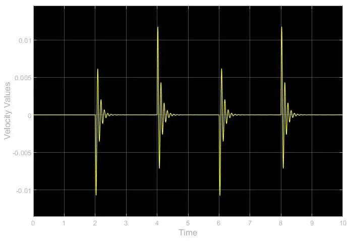
- Velocity Values vs. Time:
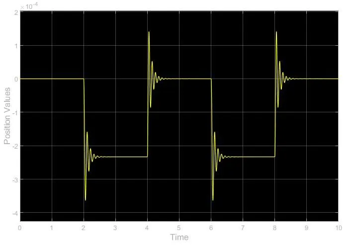
- Position Values vs. Time:
Blocks used to Thermistor based heater fan control Simulink Model:
- Signal Builder - Used to provide selected inputs signal.
-
Controlled Temperature Source - represents an ideal energy source in a thermal network that can maintain a controlled temperature difference regardless of heat flow rate. The physical signal port sets the temperature difference S. A positive temperature difference causes the temperature at port B to be greater than the temperature at port A.
-
Thermistor - This block represents an NTC thermistor using the B-parameter equation. The resistance at temperature T is given by R(T) = RO*exp(B*(1/T-1/TO)) where RO is the Nominal resistance at the reference temperature TO, and B is the Characteristic temperature constant. The temperature T of the Thermistor is governed by the equation m*c*dT/dt = Q where Q is the net heat flow into port A, m is the mass, and c is the lumped specific heat capacity. The thermal mass m*c is calculated from the Thermal time constant t_c and the Dissipation factor K_d using the equation m*c= K_d*t_C.
-
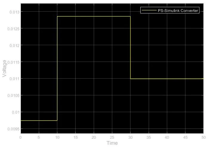
Voltage Sensor - It is a device that converts voltage measured between any electrical connections into a physical signal proportional to the voltage.
-
Resistor - It is connected to measure the voltage with a minimal connected load. Resistance has a constant value.
-
Controlled Voltage Source - It's an ideal voltage source that is powerful enough to maintain the specified voltage at its output regardless of the current passing through it.
-
Switch - it will give continuity at once it reaches its threshold value.
-
Ideal Rotational Motion Sensor - it is a device that converts an across variable measured between two mechanical rotational nodes into a control signal proportional to angular velocity or angle. The sensor is ideal since it does not account for inertia, friction, delays, energy consumption, etc.
-
Electrical Reference - To ground the electrical model.
- Battery - To provide electrical supply to the Thermistor.
-
Thermal Reference - This represents a reference point in a thermal network where the temperature equals absolute zero.
-
Mechanical rotational reference - represents a mechanical rotational reference point, that is, a frame or ground.
-
DC Motor - This block represents a DC motor's electrical and torque characteristics. The block assumes that no electromagnetic energy is lost, and hence the back-emf and torque constants have the same numerical value when in SI units. Motor parameters can either be specified directly or derived from the no-load speed and stall torque. If no information is available on armature inductance, this parameter can be set to some small non-zero value. When a positive current flows from the electrical + to - ports, a positive torque acts from the mechanical C to R ports. Motor torque direction can be changed by altering the back-emf or torque constant sign.
-
Solver configuration - Defines solver settings to use for simulation.
-
Simulink-PS converter - converts the Simulink input signal to a Physical Signal.
-
PS-Simulink Converter - Converts the Physical input Signal to a Simulink output signal.
-
Display - to display the voltage value.
-
Scope - To plot the temperature, voltage, velocity, and angular displacement values.
-
Constant - Provides a constant value input.
Block Diagram of Thermistor based heater fan control Simulink Model:
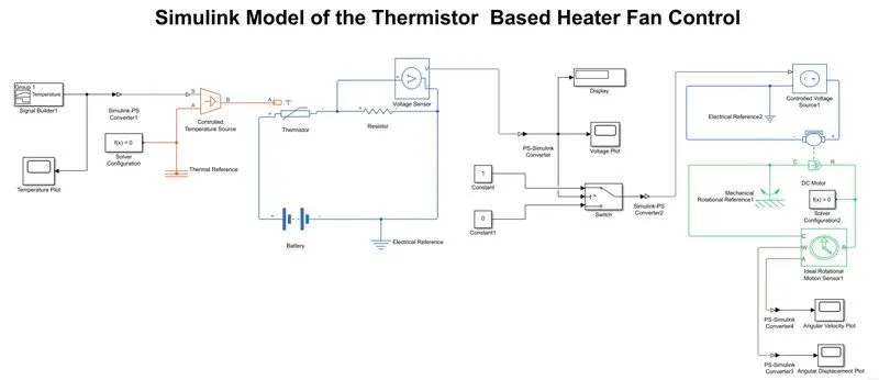
Results of Thermistor based heater fan control Simulink Model:
- Signal Builder:
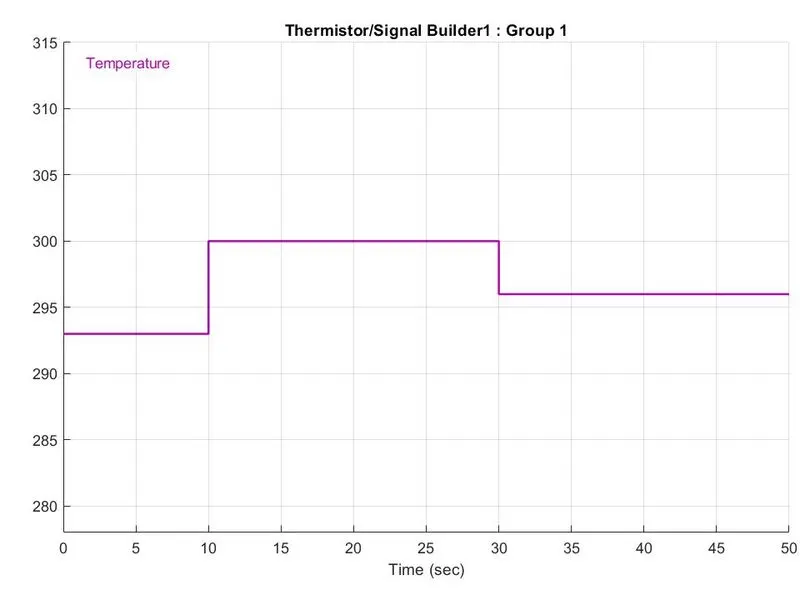
- Temperature vs. Time:
- Voltage Values vs. Time:
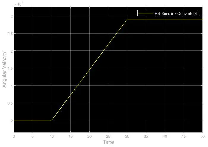
- Angular Velocity Values vs. Time:
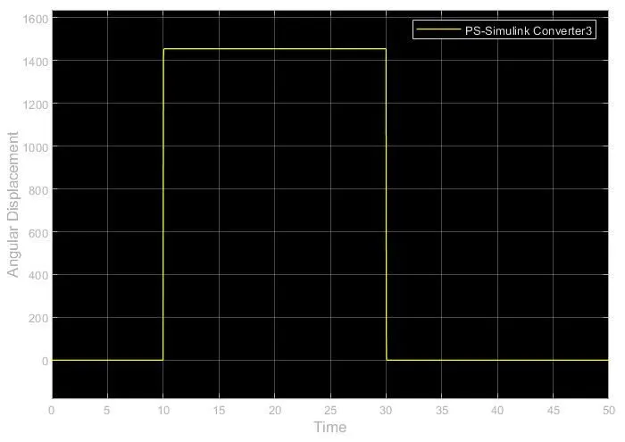
- Angular Displacement Values vs. Time:
Links for the Modules:
https://drive.google.com/file/d/1aMUdiAoBw2E3vMuSTYYvOXanMfyRNn6H/view?usp=sharing
https://drive.google.com/file/d/1ZDvmyglzFJFU-Zfg0uJYwUw3Rb7xF-rV/view?usp=sharing