Simulink Model For Electric Doorbell and Temperature controlled Fan.
DOORBELL AND TEMPERATURE CONTROLLED FAN
AIM:
- Make a Simulink model of Doorbell using solenoid block.
- Use a thermistor to sense the temperature of a heater & turn on or turn off the fan.
OBJECTIVES:
-
Make a Simulink model of Doorbell using solenoid block with the following details,
- Create a situation where the switch is closed for 2 seconds and then released. Observe the physical movement of the plunger.
2. Use a thermistor to sense the temperature of a heater & turn on or turn off the fan
- Temperature source: 20 °C from 0 to 10 seconds, 27 °C from 10 to 30 seconds, 23 °C from 30 to 50 seconds.
- Fan conditions: ON if the temperature above 25 °C, OFF otherwise.
Make a Simulink model of Doorbell using solenoid block
THEORY
Doorbell:
- The electric doorbell which we all have observed in our day-to-day life is said to be a simple circuit that triggers a sound on the completion of a circuit by pressing the button. It is said to be this simplicity that makes the doorbell such a marvel. Simple devices like the doorbell in the house put the scientific principle of electromagnetism into action in a useful way.
Circuit of an Electric Bell:
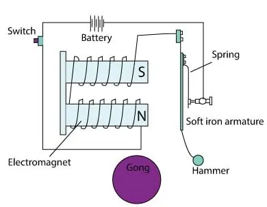
- Once the setup is completed when the switch is pressed then the circuit loop is complete which causes the flow of current through the circuit. The arm which generally strikes the gong is connected to spring at one end and a ball of iron at the other end. This is known as a hammer or a striker.
Solenoid:
- A solenoid is a type of electromagnet, the purpose of which is to generate a controlled magnetic field through a coil wound into a tightly packed helix. The coil can be arranged to produce a uniform magnetic field in a volume of space when an electric current is passed through it.
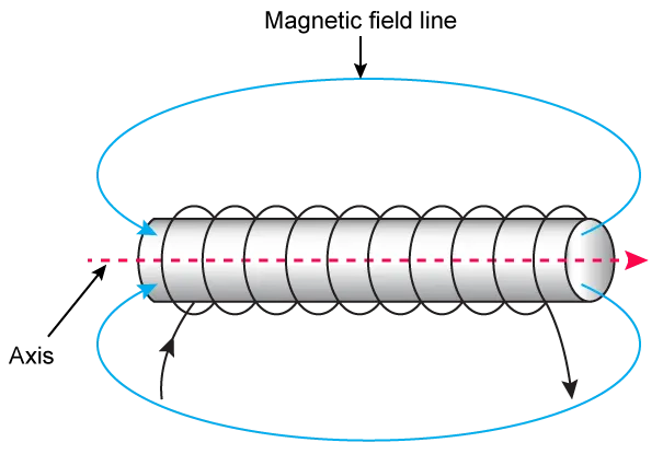
- By controlling the electric field, we can use the solenoid to operate the arm to hit the gong and make noise.
MODEL
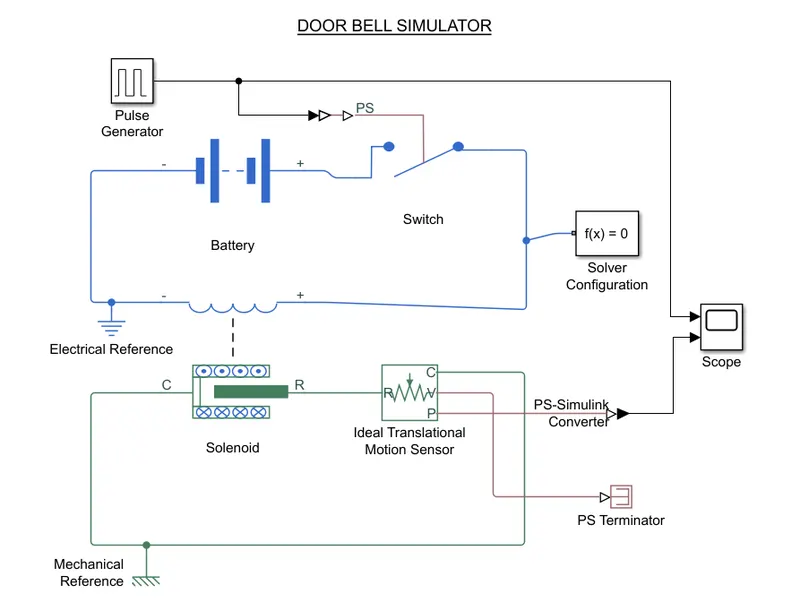
- The pulse generator block is used to generate pulses according to the objective time.
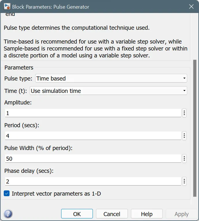
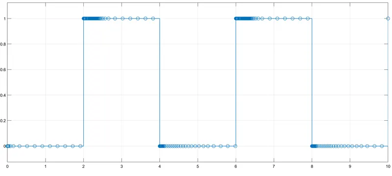
- It generates pulses with an amplitude of 1 every 2 seconds and holds for 2 seconds.
- The PS switch block is used to open and close the circuit according to the input physical signal from the pulse generator. The Simulink to PS converter block can be used to convert the Simulink pulse to a physical signal.
- The PS switch is connected to a closed circuit with the battery and solenoid, and grounded by an electrical reference block.
- The mechanical part of the solenoid is connected with a Translational motion sensor block, which can sense the translational motion and give physical signals as output
- And is grounded with a mechanical reference.
- Since we only need the sensed position from the sensor, we need to turn off the velocity output, so the PS Terminator is used.
- Since the output signal from the motion sensor and the signal from the pulse generator are connected to a scope block, we can plot the signals and evaluate the simulation.
- Physical signals can be converted to Simulink using a PS to Simulink converter before connecting to the scope block.
- The parameter in the solenoid block can be changed for better translation and smoother movement of the plunger.
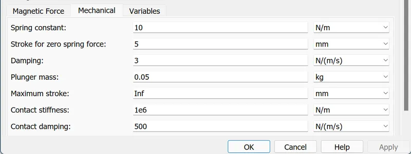
- Finally, we have linked a Solver configuration block to automatically select the Solver that best fits our model.
Results from the Scope:
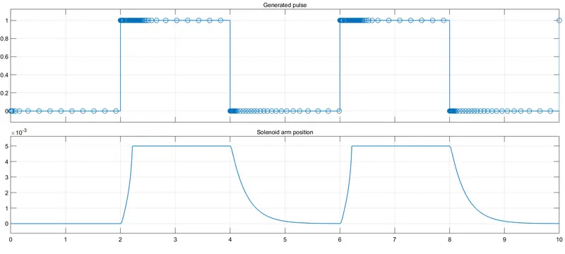
- At each pulse, the electrical circuit closes and the solenoid gets activate and move its plunger, which can be used to operate the arm or hammer.
Use a thermistor to sense the temperature of a heater & turn on or turn off the fan
THEORY
Thermistor
- A thermistor is a type of resistor whose resistance is strongly dependent on temperature, more so than in standard resistors. The word is a combination of thermal and resistor.
- Thermistors are widely used as temperature sensors. When there is heat radiation around the heat sensitive material, it absorbs the radiant heat, causing an increase in temperature, causing a change in the resistance of the material.
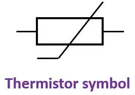
- As a thermistor sensor for measuring temperature, the structure is relatively simple and inexpensive. Thermistors without an outer protective layer can only be used in dry places.
- It can also be used as other temperature measurement and temperature control circuits by using its principle.
MODEL
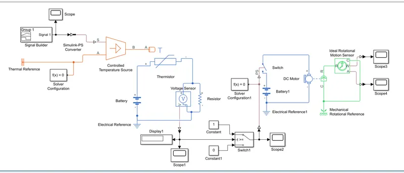
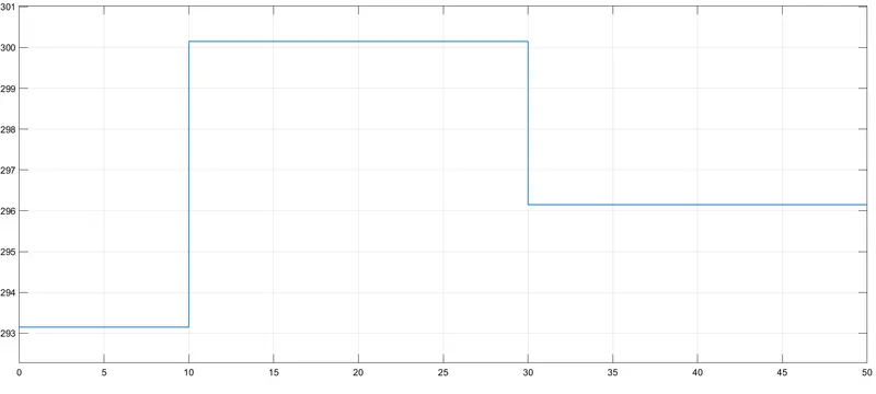
- A signal builder block is used to signal the temperature source block to provide temperature ranges according to the objectives.
- It uses the Simulink to PS converter and can see the signal with a scope. A thermal reference block is connected to the source block.
- A solver configuration block is connected with the system.
- The resistance inside a thermistor varies according to this heat source, and the voltage across the circuit also varies with temperature.
- A voltage sensor block connected in parallel to the circuit containing the battery and thermistor is used to sense the voltage across the circuit during simulation.
- The voltage can be viewed along with the circuit using the display block and the scope block.
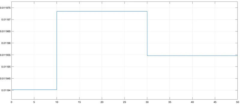
- As we can see from the plot, we can control the fan switch using these voltage differences as the voltage increases with temperature. Thus, a logical switch is created so that when the voltage rises above the threshold range the switch closes and the switch opens in all other situations.
- we can set the threshold voltage to 0.11955 so we can close the circuit and turn on the fan on at the desired temperature range (10 - 30 sec at 27°C).
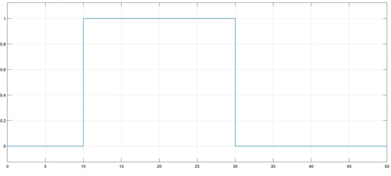
- The output from the logical switch is 1 or zero, which is connected to a PS switch. The signal 1 closes the fan's circuit and the signal zero switched off the circuit.
- The circuit for the fan contains the battery, electric reference and the DC motor connection. Mechanical rotational motion in the dc motor is understood using the rotor sensor block, which we can visualize with scopes.
- Angular velocity and angular position change can be seen using scopes.
- we need to connect solver configuration block to 2 different system.
RESULTS:
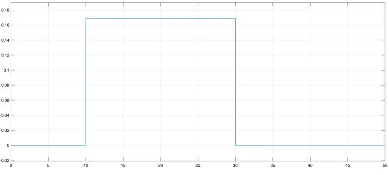
Angular velocity: (rad/s)
Angular displacement: (rad)
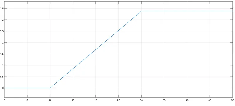
- We can clearly see that the fan starts working only when the temperature rises to 27 degrees Celsius and above (10sec - 30sec).
- Thus, the model is created for sensing temperature and turn off and on the fan switch according to the requirements.
CONCLUSION
- The Simulink model of doorbell was successfully modelled.
- The Simulink model was successfully modelled to sense the temperature of a heater and to turn the fan on or off.
REFERENCES: