Week -2
AIM: To create a simulink model for Doorbell using solenoid.
SOLENOID:It actually works on the priciple of electromagnetism. A solenoid is just a coil of wire but when a current run through, it creates an electromagnet.In terms of electrical engineering it may refer to as transducers where the electrical energy is converted in to mechanical energy.When an electric current is passed through the solenoid a magnetic field is created and this magnetic field is used to create linear motion.
The following are the blocks used in the simulink model:
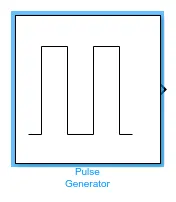
- Pulse Generator:It is used to generate the electric signal which can be used as input for the switch of required amplitude,phase delay,width and period.
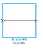
- Simulink-PS converter:This block converts simlunk signal in to physical signal for the operational use.
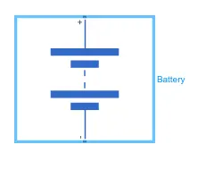
- Battery:In battery the positive terminal is connected to the switch and the negative terminal is connected to electrical reference.
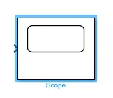
- Scope:It helps to examine the acquired output and examine the graph.
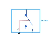
- Switch:It is given with a signal which has higher threshold than itself to perform the closed circuit operation and as well as open circuit when the input signal is not passed through it.
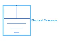
- Electrical reference:Electrical conserving ports of all the blocks which are directly connected to the groung has to be connected to the electrical reference.
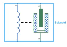
- Solenoid:Solenoid is connected to the electric battery and switch to perform the electric circuit.
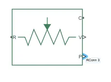
- Ideal translation motion sensor:The 'R' port which represents the plunger is connected to the 'R' of Ideal motion sensor which has two other ports named 'V' and 'P'.
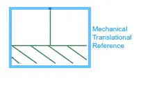
- Mechanical translation Reference:This represents the mechanical reference where all the mechanical fixed points has to be connected to this reference.
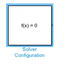
- Solver Configuration:It specifies the solver parameters required for the model before the simulation begins.
SIMULINK MODEL OF A DOOR BELL USING SOLENOID
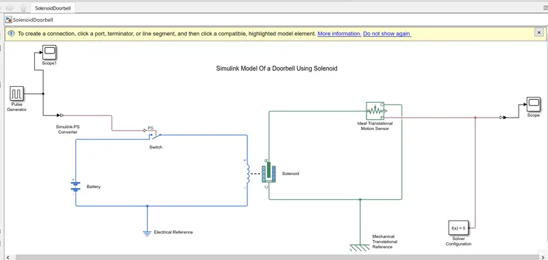
In the above image we can see the block arrangement of a doorbell using solenoid.
Explaination:
- From the given circuit diagram,one can understand that a switch,battery,solenoid and plunger is needed.
- So we have selected the blocks which perform the same operation where the objective of a given circuit can satisfy.
- Initially a pulse generator block is used to generate a electric signal of desired width,period,phase delay and amplitude so that it can have a greater threshold than the switch to make it as closed circuit which can perform the required action.A 'Simulink-PS convertor' is introduced between the pulse genrator and the switch to convert simulink signal in to required physical signal
- A scope is used to the pulse generator to examine the related amplitude,phase delay,period and width of a generated signal.
- A solenoid block is used to represent the solenoid in the simulink model and a battery block have been taken from the library browser.
- A switch is placed in between the solenoid and battery with a veiw to provide the required electric charge for the solenoid to push the plunger in specified direction.
- A electric reference is connected to the negative terminal of a battery ensure grounding for all the electrical elements used.
- The negative and positive terminals of solenoid is connected to the respective terminals of the battery to complete the electric circuit.
- Then in the solenoid the 'R' represents the plunger and port 'C' represent the fixed point of solenoid.
- The port 'R' is connected to the 'Ideal translation motion sensor' block so it can read the plunger movement and gives the output.In 'Ideal translation motion sensor' the ports 'V' and 'P' represents the velocity and position of the plunger.Since we are interested in only the position of the plunger,the port 'P' is connected with a simulation solver to sense the acquired output.
- Now the 'C' of ideal translation block is connected to 'Mechanical trnaslation reference',which represents the fixed point.
- Even the 'C' of solenoid is connected to 'Mechanical translation refernce' as fixed point for solenoid.
- Then a scope with a PS simulink converter is used to sense the output and to read the obtained graph.
- Finally to give a physical signal to the switch ,parameters of the pulse generator block has to be changed according to our required condition as shown below:
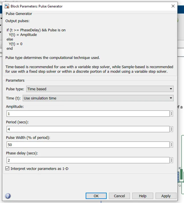
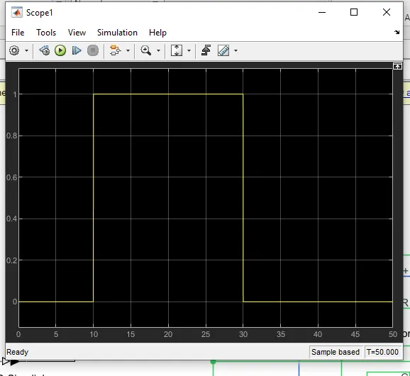
So from the above the figure you can see that we had given the period as 4 with the phase delay as 2 sec and the amplitude as 1.In this intially the pulse will remains zero till 2 seconds since the given delay is two,s this the pulse width will be half of the period and the amplitude will remain as 1 till the next 4 sec and it again comes to zero then pulse increses and cycle continues.The below image will display the acquired pulse for the given inputs.

From the above figure we can understand that when amplitude is '1' the circuit will be closed and the current flows through the switch and it will be open when amplitude is '0'.Since we need to see the position of plunger after 2 sec,the pulse width has made half of the period with delay of 2 sec.
Then as we said above the 'P' port of 'Ideal translation motion sensor' is connected to the scope with PS simulink converted to examine the plunger position.The image of this has shown below:
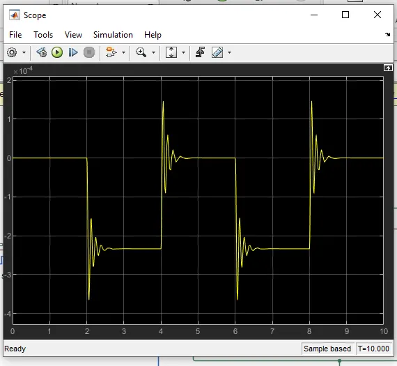
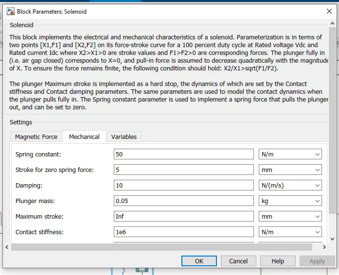
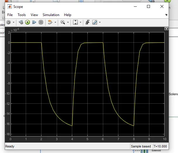
In this image 'X' axis represents times and 'Y' axis represents the plunger posittion in mm.So here initially the position of plunger will be at 5mm as we can see from the figure.As the pulse generator gives the pulse with the delay of 2 sec the position of plunger changes to perform the required action till the amplitude is 1 i.e until for 4 sec.Again the plunger return to the original position when amplitude is '0'.It will starts after the pulse intiatetes once more to continue the cycle.But we can see that there is a vobration while starting the very next cycle,this is due to the recoil of spring.This can be changed by reducing the spring constant and increasing the damping coefficient.
The below image displays the reduced spring constant and increased damping coefficient parameters.
Finally the smooth graph is obtained after changing the values of spring constant and damping coefficient which is as shown below in the graph:
THERMISTOR
Aim:On and Off a fan with a threshold temperature using thermistor.
Condition:On if tmeperature is above 25 degree celsius,Otherwise off.
Introduction:Thermistor is a combination of word thermal and resistor.It mainly depends on increase or decrese in temperature.There are two types of thermistors.They are NTC(Negative temperature coefficient) thermistor and PTC(Positive temperature coefficient) thermistor.
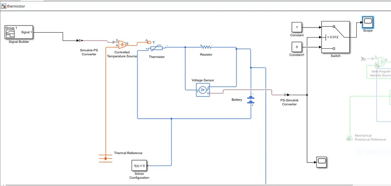
The first half represents the vlotage output acquired for the given conditions.
The input has been feeded through signal builder which includes the given three temperature coefficients(20,27,23) in celsius over the period of 50 seconds.The signal builded have been shown below:
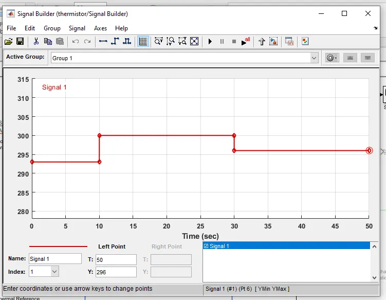
From the signal builder it has been connected to controlled temperature source through Simulink PS converter.
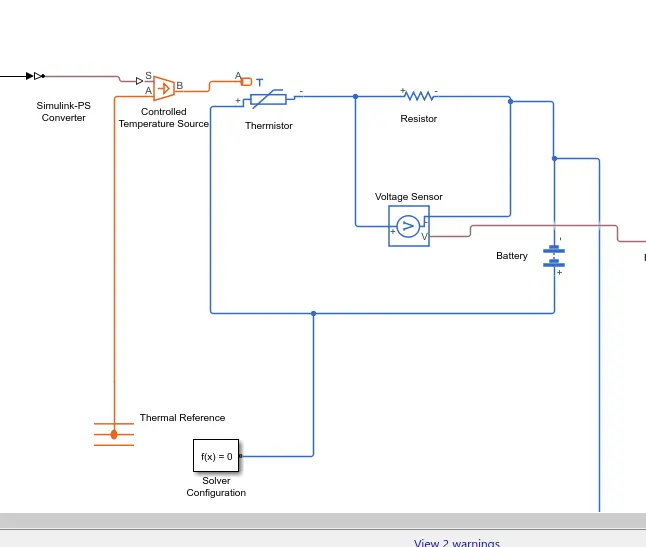
- From the above image we can see that,the controlled temperature source has been connected to the thermistor and a resistor,a voltage sensor has been connected parallel to the resistor to sense the voltage passing through it.
- A thermal reference has been included for the controlled temperature source and an electrical reference is used to ensure grounding.
- A solver configuration has been provided to the circuit.
Then,
The output the voltage sensor has been connected to the switch to check and satisfy the given condition.The threshold value of voltage at 25 degree celsius is 0.012V .If the temperature exceeds the threshold,gives out zero.If it is less than threshold,gives output value.
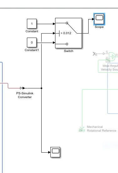
The output scope of a switch has been shown below:
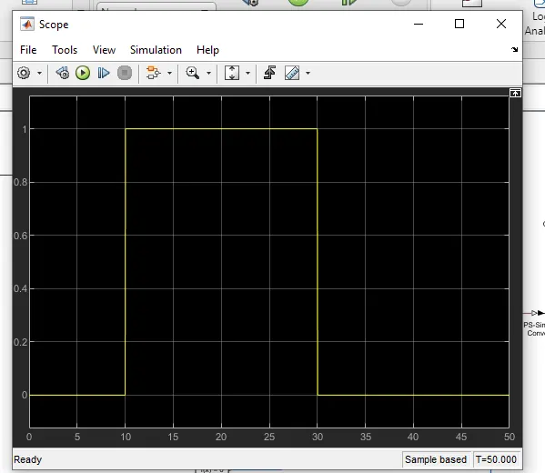
Then the pulse generated has been given to DC mottor/fan as below:
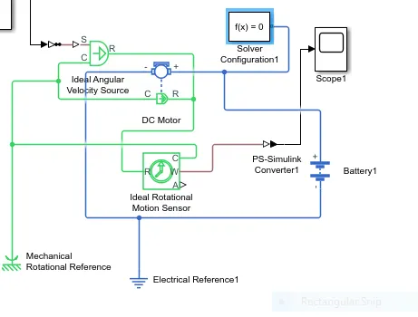
- Output from the switch has been connected to velocity source and then to the DC motor with the help of battery.
- To plot the motion of fan,ideal rotational motion sensor has been placed.
- Mechanical and electrical references along with the solver configuration has been provided.
- The output of DC motor has been seen out by the scope connectedat the end which confirms our condition.The output of the scope is shown below.