Week -2
Aim: To make a Simulink model of doorbell using solenoid block
In the above arrangement, when the switch is closed the electromagnet receives electrical power from the battery and pulls the metal arm to hit the bell producing sound.
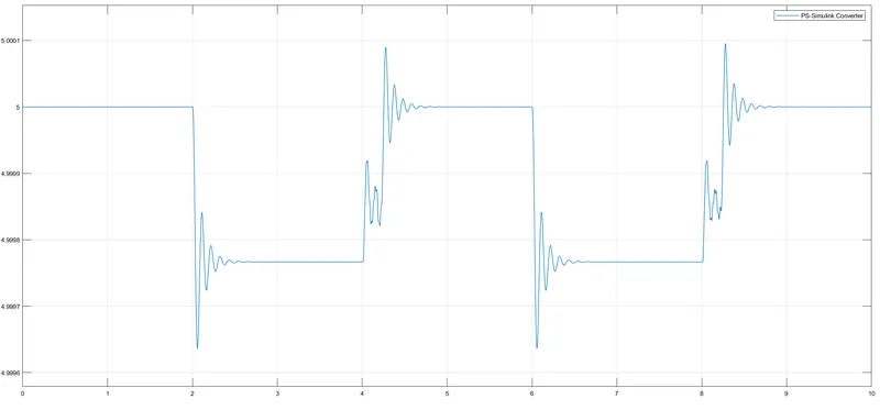
Create a situation where the switch is closed for 2 seconds and then released. Observe the physical movement of the plunger.
1. Doorbell:
When the door bell button is pressed, an electric circuit is closed which leads to the flowing of electric current through the electromaganet. The current then passes through the electromagnetic wire winding. A magnetic field is generated as a result, which is used tp drive a sound making mechanism. Different types of sound making mechanism are used to generate different sorts of noises.
Procedure:
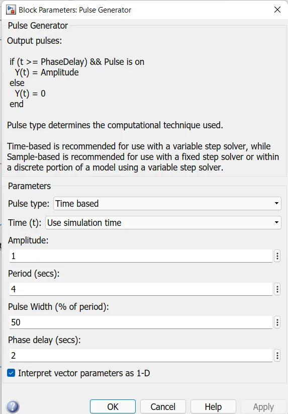
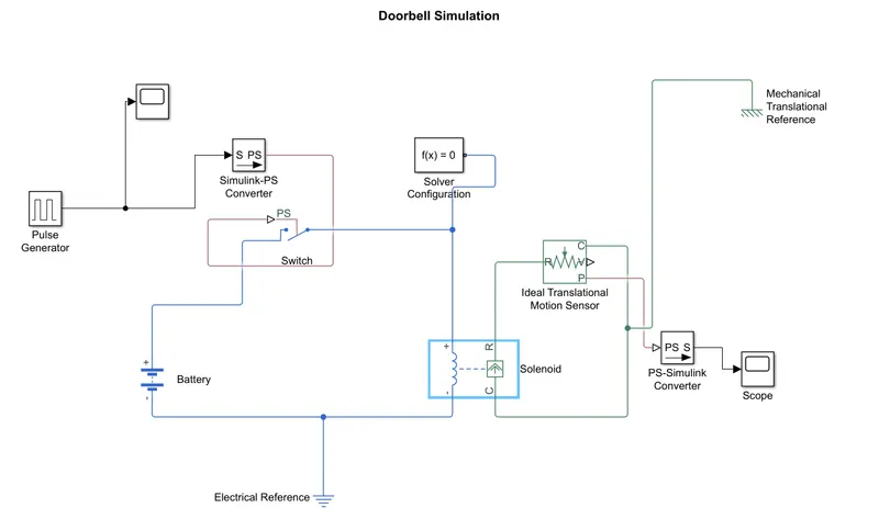
- First the input is given with the help of pulse generator and it is connected to electrical switch with the help of simulink-ps converter and the input is observed by connecting scope.
- then the solver configuration block is connected to switch.
- battery block is defined for voltage source.
- the battery is connected to an electrical switch and the switch is connected to the solenoid to complete the circuit.
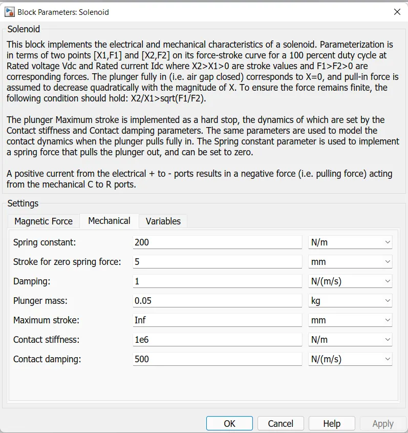
- then we give the block for solenoid and connect it to an ideal translational motion sensor to measure the translational motion of the solenoid, and the traslation motion of the bell is obseerved by connecting it to scope with the help of ps-simulink conveter.
- electrical reference and mechanical translation reference connected as earthing.
- stop time is 20 sec
- Initial position of the ideal translational motion sensor is given as 5
Parameters
Pulse generator block
Solenoid block
Simulink model for Door bell
Output scope
2.Aim:
To Use a thermistor to sense the temperature of a heater & turn on or turn off the fan as per the below conditions:
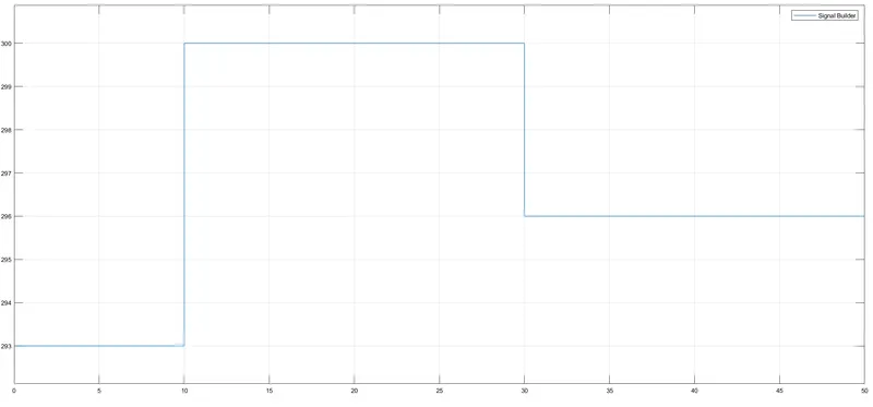
Temperature source: 20 °C from 0 to 10 seconds, 27 °C from 10 to 30 seconds, 23 °C from 30 to 50 seconds
Fan conditions: ON if the temperature above 25 °C, OFF otherwise
Thermistor:
A thermistor is a resistance thermometer, or a resistor whose resistance is dependent on temperature. the term is a combination of "Thermal" and "resistor". It is made of metallic oxides, pressed into a bead , diskor cylindrical shape and then encapsulated with an impermeable material such as epoxy or glass.
There are two types of thermistor: Negative temperature Coefficient (NTC) and Positive Temperature Coefficent (PTC). With an NTC thermistor, when the temperature increases, resistance decreases. conversely, when the temperature decreases, resisance increases. This type of thermistor is moslty used.
A PTC thermistor works little differently, when temprature increases, the resistance increases, and when the temperature decreases, resistance decreases. This type of thermistor is mostly used as fuse.
Typically, a thermistor achieves high precision within a limited temperature range of about 50 degree celcius around the target temperature. This range is dependent on the base resistance.
Procedure:
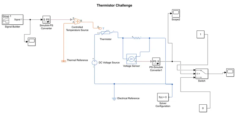
- first we give the input signal wih the help of signal builder block.
- the input signal block is connected to 'S' port of the controlled temperature source block with the help of simulink-ps converter. the 'B' port of the controlled temperature source is connected to the 'A' port(net heat flows through port A) of thermistor.
- A scope is connected to the input signal to observe the input.
- then we make a thermistor block and connect a battery to it as a voltage source.
- then we connect a resitor block and connect it to a voltage block in series to measure the voltage flowing through the resistor.
- display block is connected to "V" (V is the physical port that outputs the voltage value) of the voltage sensor with the help of ps-simulink converter to display the output.
- a conditional switch block with 2 costants blocks of value "0" and "1" is connected to the "V" port of the voltage sensor.
- the threshold of the switch is calculated with the help of thermistor equation
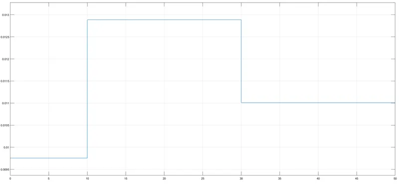
B(T1/T2) = (T2*T1)/(T2-T1) * ln(R1/R2) - 0.012 volts is calculated as the threshold at 25 degree celcius and it gives the threshold for switch.
- T1 is the first temperature point in Kelvin
- T2 is the second temperature point in kelvin
- R1 is the thermistors resistance at temperature T1
- R2 is the thermistors resistance at temperature T2
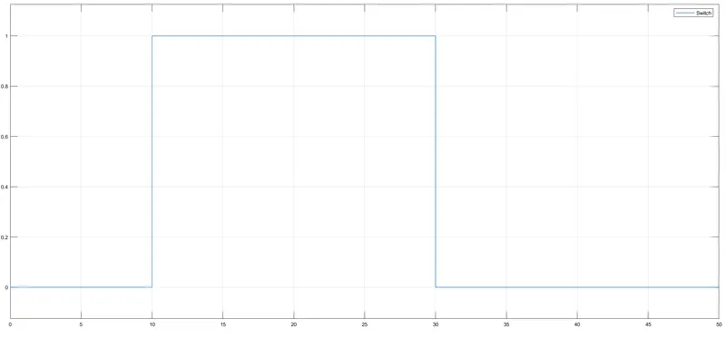
- The conditional switch block is connected to scope to display the graph and the output of switch is connected to a lamp. the lamp glows red if the resistance across is less than the switch threshold meaning the fan is off, if the resistance across is higher than the switch threshold the lamp glows green meaning the fan is on.
- thermal reference and electrical reference is connected to provide earthing.
- the initial stop time is given as 20 Seconds
Simulink model
input scope
output scope