Doorbell using a solenoid block & thermistor to sense the temperature of a heater & turn on or turn off the fan
- Make a Simulink model of Doorbell using a solenoid block with the following details
In the above arrangement, when the switch is closed the electromagnet receives electrical power from the battery and pulls the metal arm to hit the bell producing sound.
Create a situation where the switch is closed for 2 seconds and then released. Observe the physical movement of the plunger.
Assume remaining parameters.
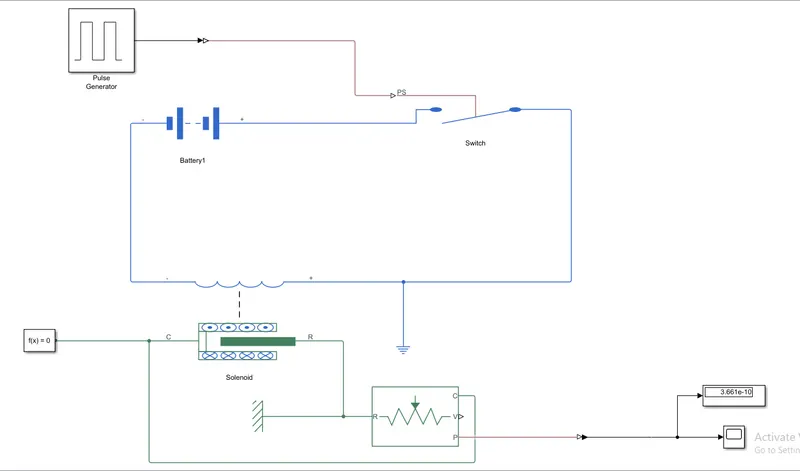
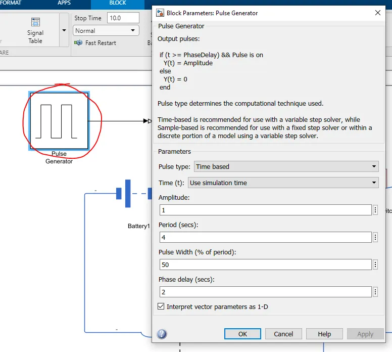
Pulse generator will generate the frequency of pulse for time being as shown above the delay is 2 sec
.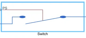
The pulse generator will give the input for the switch for every 2 sec to ring the bell
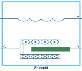
Electrical characteristics and generated force of solenoid Port R moves towards port C
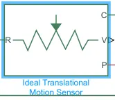
This block measures velocity or displacement in a mechanical translational network. The sensor is ideal since it does not account for inertia, friction, delays, energy consumption, and so on.
The physical signal ports V and P report the velocity and position, respectively, of port R relative to port C. The measured velocity is positive when the velocity at port R is greater than the velocity at port C.
RESULTS
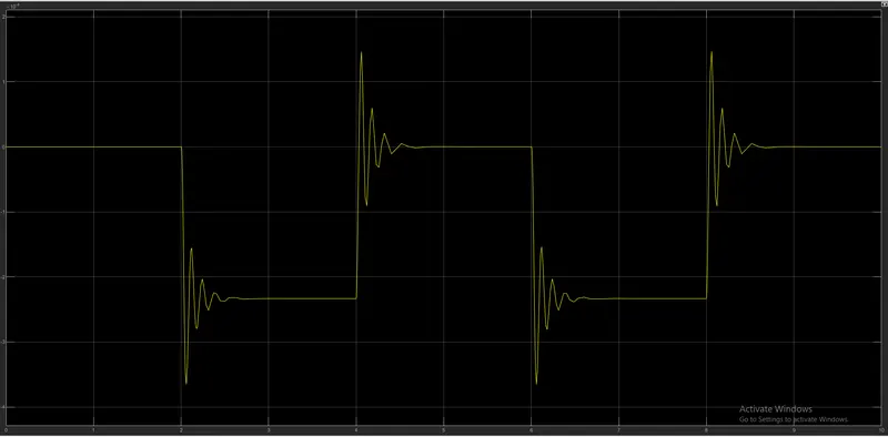
We can see the graph the plot is increased and decreased for every 2 sec and also the sock waves also
2. Use a thermistor to sense the temperature of a heater & turn on or turn off the fan as per the below conditions
Temperature source: 20 °C from 0 to 10 seconds, 27 °C from 10 to 30 seconds, 23 °C from 30 to 50 seconds
Fan conditions: ON if the temperature above 25 °C, OFF otherwise
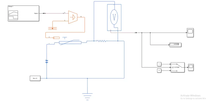
Step1: Identify the problem statement and condition logic to be implemented.
In the above question, we observe there is a thermistor to sense the heat, and based on this heat there is a fan that should be ON & OFF.
Condition: Input - 0 to 10 sec temp is 20 °C Output - Fan should be ON only > 25 °C
10 to 30-sec temp is 27 °C else OFF
30 to 50-sec temp is 23 °C
Step2: List out all the blocks required for the problem. For this challenge, the requirements are listed below
- Signal Builder - to generate the signal according to the input condition given.
- PS-Simulink converter: Converts Simulink signals to the respective physical signal.
- Controlled temperature source: (CTS) Provide a temperature physical output based on the condition given to port S.
- Thermal reference: Thermal reference block provides the required initial conditions to the connected thermal block for the solver.
- Thermistor: Thermistor block which shows us the NTC thermistor relation between temperature and resistance.
- Battery: Battery is a storage device that provides the required voltage based on the parameter given. We can use DC voltage source blocks too.
- Resistor: Resistor which provides the opposing nature of current in a circuit.
- Voltage sensor: This is used to measure the voltage or potential difference across any electrical component and it should connect in parallel only.
- Electrical Reference: These domain-specific electrical reference blocks will provide the required initial conditions to the connected thermal block for the solver.
- Solver Configuration: The Solver Configuration block specifies the solver parameters that your model needs before you can begin simulation and this is mandatory for all simscape designs.
- PS-Simulink Converter: Converts physical signals to the respective Simulink signal.
- Constant: Provides a constant output value
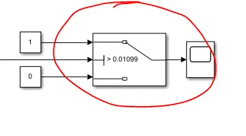
- Switch: This block is used from the library Simulink / Signal Routing where it has three inputs namely Port1, Port2, and Port3. Port2 is a control input where the signal given to port2 is satisfied with the condition and threshold of the switch block then it passes Port1 as output and if it is not satisfied then it will pass Port3 as output.
- Scope: This is an output block that shows the signal with respective time in an X-axis.
Step3: Connect signal builder(create given temperature condition in it) to thermistor using controlled temperature source and connect a resistor along with voltage source. Check the voltage across the resistor and note the respective voltage value for 25 °C. Use the noted value as a threshold for the switch block and produce the output signal.
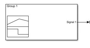
Signal builder
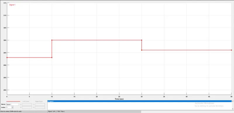
INPUT SIGNALS IN SIGNAL BUILDER
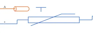
THERMISTOR
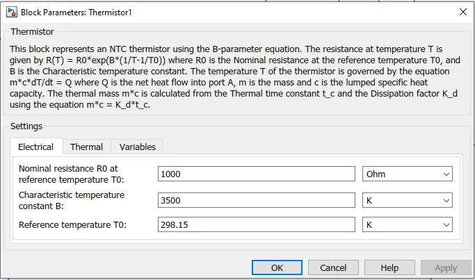
The thermistor will give the value for the 25 degrees (298.15 k) as shown in above fig
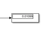
DISPLAY
IN display we will get the solver value for the 25 degrees so that we can give the threshold value that when should the fan to on and off
SWITCH
We give the constants of 1 and 0 where we are saying the switch that if the solver value is above 0.01099 ON if the value is below the fan to OFF
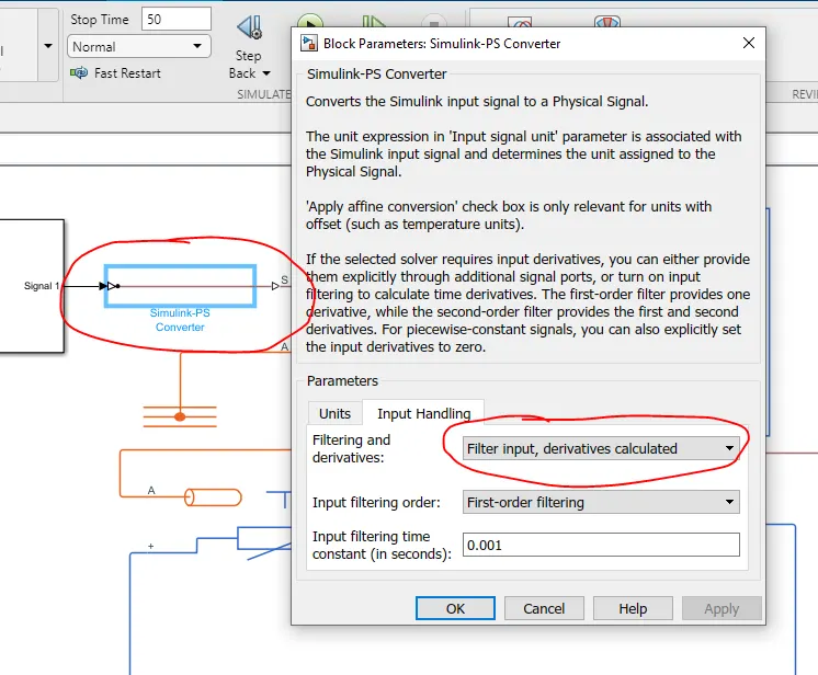
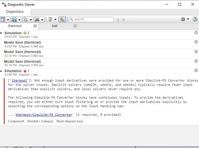
The above setting should be done or else it will throw an error as shown below where it cant solve for the provided signals because the implicit solver requires the minimum inputs to solve
RESULTS
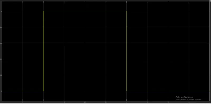
Where the value 1 indicates the fan is on and 0 is off