Week -2
AIM:
1. TO MAKE A SIMULINK MODEL OF DOORBELL USING SOLENOID.
2. TO USE A THERMISTOR TO SENSE THE TEMPERATURE OF A HEATER AND TURN ON OR OFF THE FAN AS PER CONDITIONS.
OBJECTIVE:
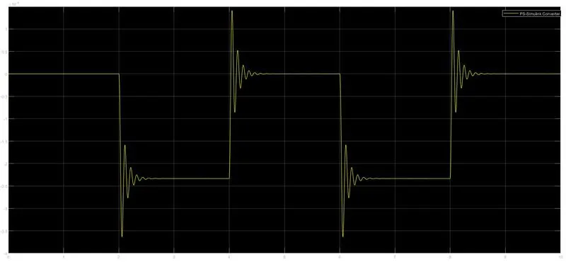
1. To create a situation where the switch is closed for 2 secs and then released. Observe the physical movement of the plunger.
2. To sense the temperature of a heater by using condition -
Temperature source Time frame
20°C 0 - 10 sec
27°C 10 - 30 sec
23°C 30 - 50 sec
Fan Condition: ON if the temperature is above 50°C, OFF otherwise
THEORY:
1. Door Bell
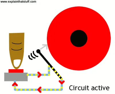
When you press a doorbell button, you complete an electrical circuit to flow through the doorbell's electromagnet. When the electricity flows through the electromagnet, it gets energized due to the magnetic field and attracts the hammer towards it and it strikes the gong. By this, the other part of the electromagnet gets disconnected and the circuit gets break. As the circuit breaks, it again comes to its original position and the same process is repeated till the switch is pressed.
2. Temperature sensing using Thermistor
A thermistor is defined as a type of resistor whose electrical resistance varies with change in temperature. Although, all resistors' resistance will fluctuate slightly with the temperature a thermistor is particularly sensitive to temperature changes. It's a semiconductor that has a resistance capacity more than a conducting material and less than insulating material.
There are mainly 2 types of thermistors, namely 1. Negative Temperature Coefficient (NTC Thermistor) and 2. Positive Temperature Coefficient (PTC Thermistor).
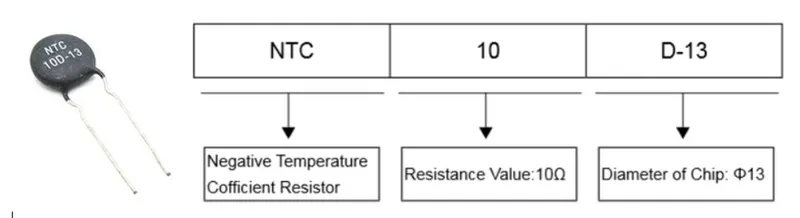
Thermistor's relation with temperature also depends on which type of material it's made OFF. An NTC Thermistor will decrease its resistance value when temperature increases, whereas a PTC Thermistor will increase its resistance when the temperature is increased. They have sigh sensitivity which can be up to 10% change per degree Celcius and their typical response time is 0.5 to 5 secs with an operating range from -50°C to 300°C and there are devices with more capacity.
How to read a thermistor value.
CIRCUIT SIMULATION & EXPLANATION:
1. Door Bell -
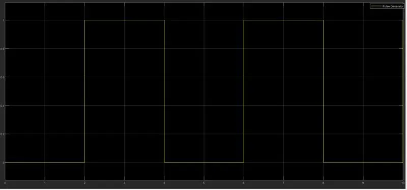
Here, we're giving input through the Pulse Generator, which generates square waves at regular intervals. Amplitude, Pulse Width, Period and Phase Delay determine the shape of the output waveform. The Pulse Generator is connected with Simulink to Physical system Convertor (converts Simulink signals into signals which could be understood by the physical systems.) and with a Scope (to check the wave generated by the pulse generator.). After this, there's a push-button switch that is connected to a Solenoid and an Electrical Reference. To check the motion of the solenoid there's an Ideal Translational Motion Sensor which is connected to Mechanical Translational Reference and Solver Configuration (specifies the configuration which the model needs for the simulation). After this, there's a Physical System to Simulink Converter (converts signals produced by physical systems to signals that could be understood by the Simulink) and a Display (to display the Output) and a Scope.
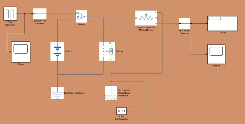
In this simulation, the Solenoid Block represents the electrical characteristics and generated force for the solenoid. It converts the electrical characteristics to mechanical.
C – denotes CASE MECHANICAL
R – denotes PLUNGER MECHANICAL
The plunger (R) of the solenoid is connected to the R of the Ideal Mechanical Translational Motion Sensor.
The Solver Configuration is connected for the execution of the circuit without error.
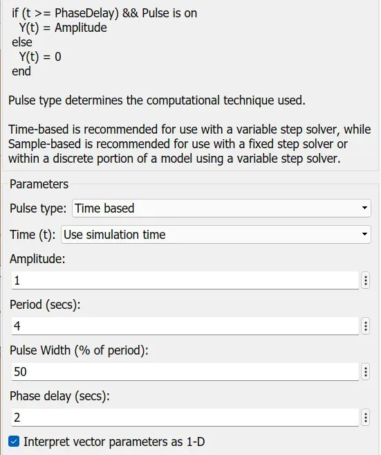
In the given task, the amplitude of the wave is 1, the circuit is powered by a battery via a switch with 2 seconds ON time. So, the total time period (Period) will be 4 seconds and the Pulse Width would be for 2 secs, i.e. 50% of the Total Time Period and delay is 2 seconds.
INPUT PULSE -
OUTPUT PULSE -
2. Temperature sensing using Thermistor -
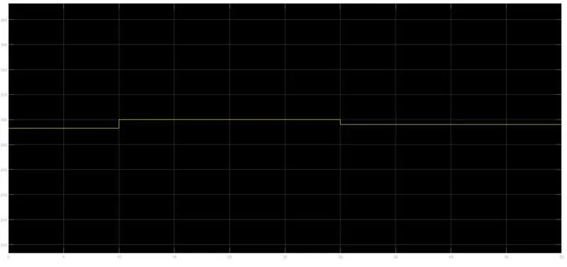
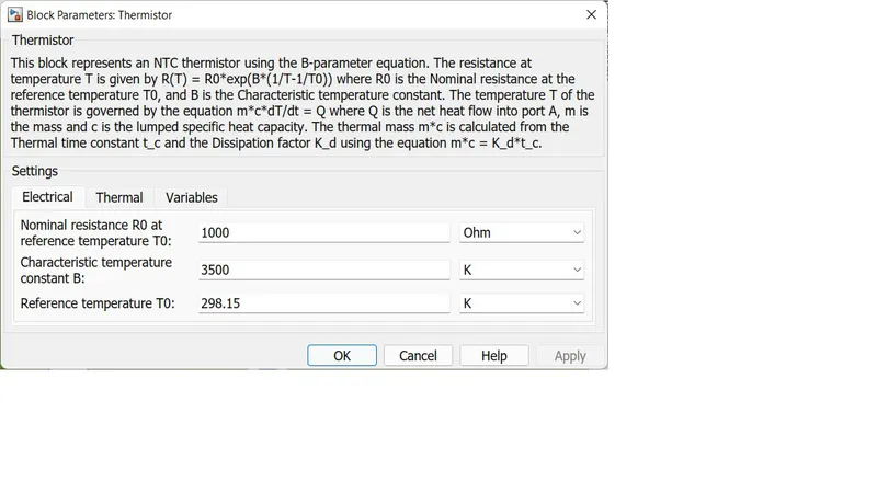
In this, we're giving an input signal through Signal Builder to generate the required signal. It is then connected to Simulink to Physical system Convertor (converts Simulink signals into signals which could be understood by the physical systems) and with a Scope (to check the wave generated by the pulse generator). After that, we've Controlled Temperature Source (to maintain the specified temperature difference across the source regardless of the heat flow consumed by the system) with Solver Configuration (specifies the configuration which the model needs for the simulation) and a Thermal Reference (represents a thermal reference point, that is, a point with an absolute zero temperature, with respect to which all the temperatures in the system are determined). The Thermistor is connected through inlet point A to outlet point B of the Controlled Temperature Source. The simulation is powered by a Battery. Then, we have a Voltage sensor (converts voltage measured between two points of an electrical circuit into a physical signal proportional to the voltage) and a Resistor and Electrical Reference. After that, we've Switch, which has 3 inputs. The 1st and 3rd inputs are data inputs (1 & 0) which are coming from Constant Blocks and the 2nd input is a control input which is coming from Physical System to Simulink Converter (converts signals produced by physical systems to signals that could be understood by the Simulink) which is also connected to the Voltage Sensor. The Display is connected to the 2nd input pin of the Switch and a Scope is connected at the output of the Switch.
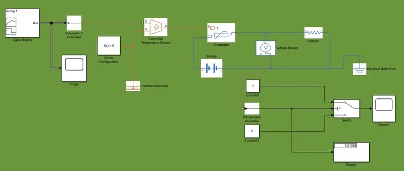
INPUTS -
Signal Builder
In signal builder, we've to custom input the signals and increase the time to 50 secs.
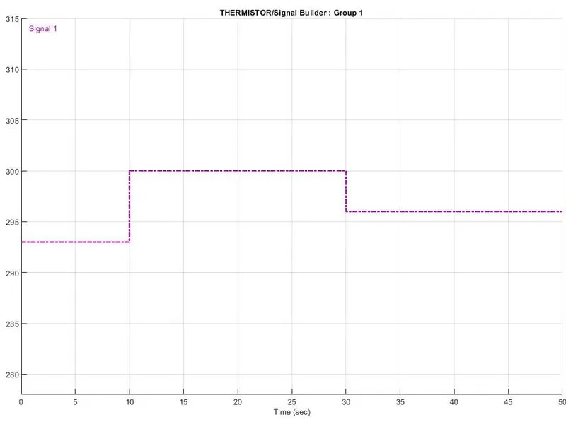
OUTPUT -
RESULT:
1. In Solenoid simulation, the motion of the plunger was simulated, recorded and plotted by using an Ideal Motion Sensor and Scope.
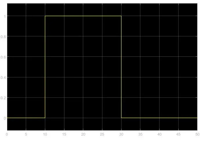
2. In thermistor simulation, we can see in the output graph that the fan remains ON till the temperature is 300k otherwise, it remains OFF.
CONCLUSION:
We can conclude that in the above simulations, we got the desired output.