Week -2
- Make a Simulink model of Doorbell using solenoid block with the following details:
In the above arrangement, when the switch is closed the electromagnet receives electrical power from the battery and pulls the metal arm to hit the bell producing sound.
Create a situation where the switch is closed for 2 seconds and then released. Observe the physical movement of the plunger.
Assume remaining parameters.
2. Use a thermistor to sense the temperature of a heater & turn on or turn off the fan as per below conditions:
Temperature source: 20 °C from 0 to 10 seconds, 27 °C from 10 to 30 seconds, 23 °C from 30 to 50 seconds
Fan conditions: ON if the temperature above 25 °C, OFF otherwise
Simulink model
1.Electric bell
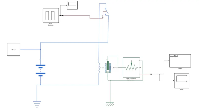
Here we simulate how the bell's arm vibrates and catch that vibration in understandable data. So we need to capture the vibration in terms of time steps.
The blocks used here are as follows
1. Pulse generator: This block is an input simulink block, where the input can be given in terms of pulses defined by us.
2. PS-Simulink/Simulink-PS converter: This converter helps to convert signals from physical state blocks to simulink blocks and vice versa. If this block isn't implemented here there will be no flow of data and we cannot connect the desired blocks.
3. Switch: A simple switch that can be used to open and close the circuit.
4. Solenoid: Here we're using a solenoid to depict the movement of the arm of the bell.
5. Battery: a power source for the entire circuit
6. Ideal translation motion sensor: this is a sensor that detects any kind of translation motion. This is used to detect the movement of the solenoid arm.
7. Display: As the name suggests displays the output in numbers.
8. scope: The scope block is used to get the graph with respect to the time step.
9. Electrical/mechanical reference: Equivalent to the ground given to electric circuits. every simulation in simulink will be seen with these references.
10. Solver configuration: Defines the type of solver to be used for the simulation.
Pulse generator details are below.
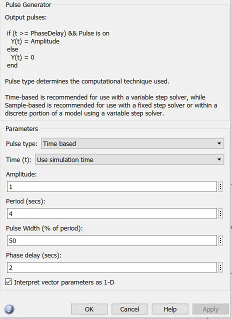
we needed a delay of 2 seconds between each pulse. So, change the period to 4 seconds and the phase delay to 2 seconds, pulse width should be 50% of the period which is 2 seconds.
Results
From the scope block, we get the below results
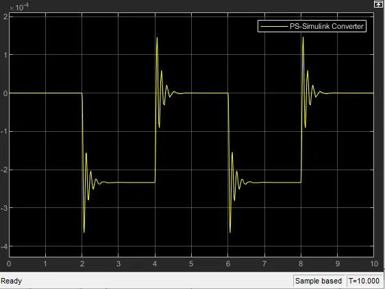
Here we can see that the graph is gone to the negative side, this just justifies that the arm(considered as a pendulum) has 3 positions. so it starts at zero, goes to one side then back to zero and then to the other side.
2. Thermistor
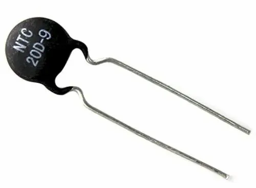
A thermistor is a type of resistor whose resistance is strongly dependent on temperature, more so than in standard resistors. The word is a combination of thermal and resistor. Thermistors are widely used as inrush current limiters, temperature sensors (negative temperature coefficient or NTC type typically), self-resetting overcurrent protectors, and self-regulating heating elements (positive temperature coefficient or PTC type typically). An operational temperature range of a thermistor is dependent on the probe type and is typically in between −100 °C (173 K) and 300 °C (573 K).
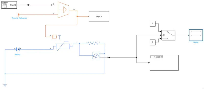
Blocks used
1. Signal Builder: This block lets us control how the input is processed in the simulation.
2. Controlled thermal source: This block, as the name suggests helps us achieve a temperature that can be controlled by the user. This block represents an ideal energy source in a thermal network that can maintain a controlled temperature difference regardless of the heat flow rate. The temperature difference is set by the physical signal port S. A positive temperature difference causes the temperature at port B to be greater than the temperature at port A.
3. Thermistor: This block represents an NTC thermistor using the B-parameter equation. The resistance at temperature T is given by R(T) = R0*exp(B*(1/T-1/T0)) where R0 is the Nominal resistance at the reference temperature T0, and B is the Characteristic temperature constant. The temperature T of the thermistor is governed by the equation m*c*dT/dt = Q where Q is the net heat flow into port A, m is the mass and c is the lumped specific heat capacity. The thermal mass m*c is calculated from the Thermal time constant t_c and the Dissipation factor K_d using the equation m*c = K_d*t_c.
4. voltage sensor: detects the voltage across the setup.
5. Resistor: The voltage-current (V-I) relationship for a linear resistor is V=I*R, where R is the constant resistance in ohms. The positive and negative terminals of the resistor are denoted by the + and - signs respectively. By convention, the voltage across the resistor is given by V(+)-V(-), and the sign of the current is positive when flowing through the device from the positive to the negative terminal. This convention ensures that the power absorbed by a resistor is always positive
6. Switch: a switch to Switch the fan (The fan itself is not added to the simulation)on and off.
7. Electrical And Thermal reference.
8. scope and display
9. Solver configuration
For the switch to work the way we want it to, we first run the sim once and get a value in the display connected to the voltmeter. this will give us the threshold voltage that we can input to the switch which will in turn behave the way we want it to, if the threshold voltage is crossed then the switch will close, if not the switch will remain open.
Below you can see that signal that was built for this simulation.
Conditions
0-10s - 20degC
10-30s - 27degC
30-50s - 23degC
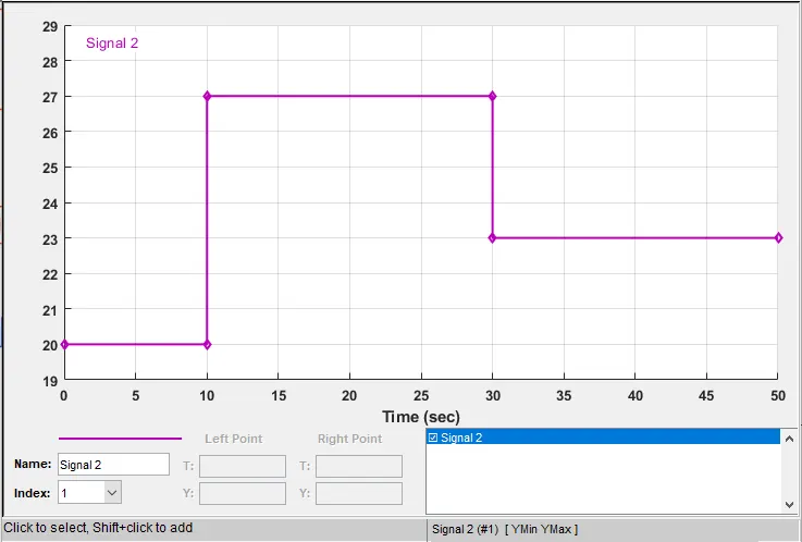
Also, note that the stop time should be changed from 10s to 50s.
Results
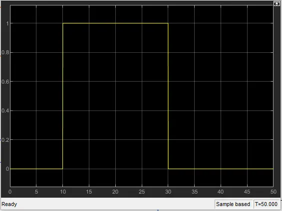
The above graph shows that the fan will be switched on from the time step 10 to 30. This is because the condition was that if the temperature crosses 25degC, then the fan should turn on. In the signal builder above you can see that from 10 to 30 seconds time step the temp is 27degC.