Week -2
AIM:
- To make a Simulink model of a doorbell using a solenoid block.
- To make a Simulink model of a temperature-controlled fan.
OBJECTIVE:
- Understand the working of a Solenoid Block (in the simulation model) & observe it's translational motion (w.r.t. to input) on a scope block with the help of a translational sensor.
- Understand the working of a Thermistor (in the simulation model) & observe the switching on & off of a fan w.r.t the change in temperature beyond a threshold value.
PROCEDURE:
Model-I: Doorbell using Solenoid Block
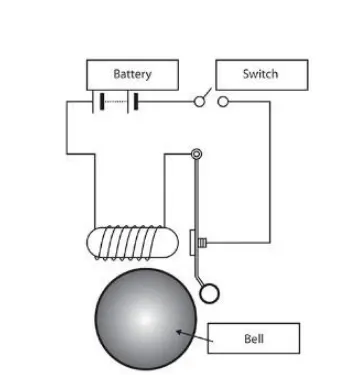
The given circuit has been converted into a simulation model in the following manner:
Simulink Model:
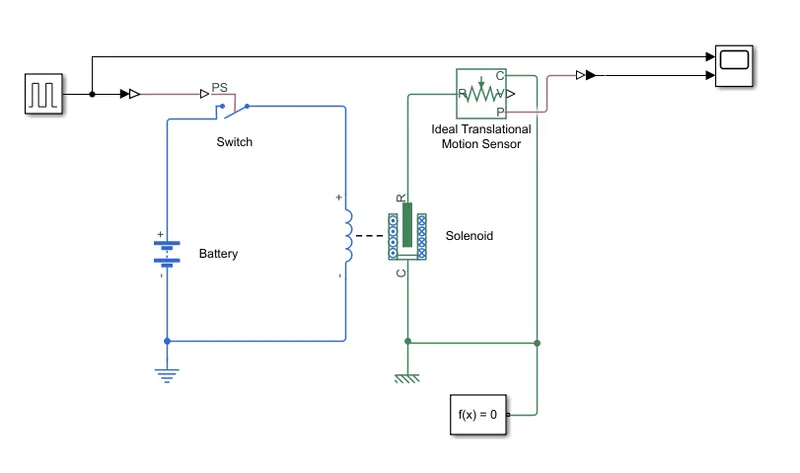
A pulse generator is used to generate square pulses at an interval of 2 seconds. The Simcape switch block receives a signal from the Pulse generator via a Simulink-PS converter. The switch is connected between a battery source and a solenoid. When the switch receives an external signal, it gets turned on, the circuit is completed. It must be noted that in this circuit the switch block is having a threshold of 0.5 and it will turn on only if the input amplitude is greater than that which is taken to be 1 in this case. The solenoid gets energized and the plunger moves towards the solenoid. The translational movement of the solenoid is measured with the help of the Ideal Translational Motion Sensor, the output signal through a PS-Simulink converter and is finally observed on a Scope block.
Blocks Used:
| Sl. No. | Symbol | Name of Block | Function |
| i |  |
Pulse Generator | The Pulse Generator block generates square wave pulses at regular intervals. The block waveform parameters, Amplitude, Pulse Width, Period, and Phase delay, determine the shape of the output waveform. |
| ii |  |
Switch-Simscape |
The block represents a switch controlled by an external physical signal. If the external physical signal PS is greater than the threshold, then the switch is closed, otherwise, the switch is open. |
| iii. |  |
Battery |
This block models a battery. If we select Infinite for the Battery charge capacity parameter, the block models the battery as a series internal resistance and a constant voltage source. If we select Finite for the Battery charge capacity parameter, the block models the battery as a series internal resistance plus a charge-dependent voltage source. |
| iv. | 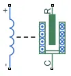 |
Solenoid |
This block implements the electrical and mechanical characteristics of a solenoid. The plunger Maximum stroke is implemented as a hard stop, the dynamics of which are set by the Contact stiffness and Contact damping parameters. The same parameters are used to model the contact dynamics when the plunger pulls fully in. The Spring constant parameter is used to implement a spring force that pulls the plunger out and can be set to zero. |
| v. |  |
Ideal Translational Motion Sensor |
This block measures velocity or displacement in a mechanical translational network. The sensor is ideal since it does not account for inertia, friction, delays, energy consumption, and so on. The physical signal ports V and P report the velocity and position, respectively, of port R relative to port C. The measured velocity is positive when the velocity at port R is greater than the velocity at port C. |
| vi. |  |
Scope |
This block displays time-domain signals. It displays its input with respect to simulation time. It can have multiple axes (one per port); all axes have a common time range with independent y-axes. It allows us to adjust the time and the range of input values to be displayed. |
| vii. |  |
Solver configuration | The Solver Configuration block specifies the solver parameters that a model needs before one can begin with simulation. |
| viii. |  |
PS-Simulink converter | The PS-Simulink Converter block converts a physical signal into a Simulink output signal. |
| ix. | Simulink-PS Converter | The Simulink-PS Converter block converts the input Simulink signal into a physical signal. | |
| x. | Electrical Reference | The Electrical Reference block represents an electrical ground. Electrical conserving ports of all the blocks that are directly connected to the ground must be connected to an Electrical Reference block. | |
| xi. | Mechanical Translational Reference | The Mechanical Translational Reference block represents a reference point, or frame, for all mechanical translational ports. All translational ports that are rigidly clamped to the frame (ground) must be connected to a Mechanical Translational Reference block. |
Output:
Observation:
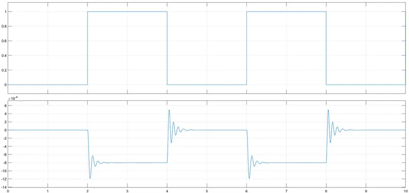
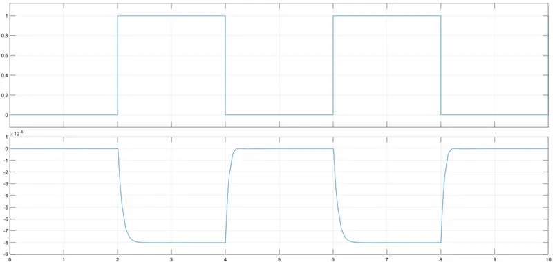
From the graph, we can observe that when the switch is turned on, the plunger is moved from its initial position and then stays at the new position for 2 seconds before getting back to the old position when the switch is turned off. The spikes/oscillations are observed due to the low value of damping(default value of 1 N/(m/s) has been taken for the output above). If we increase the value of damping in the mechanical section of the solenoid block to a higher value, we will observe that the oscillations no more exist and a smooth graph will be obtained as shown below when the value of damping has been changed to 12 N/(m/s).
Model-II: Temperature controlled fan using Thermistor Block
Simulink Model:
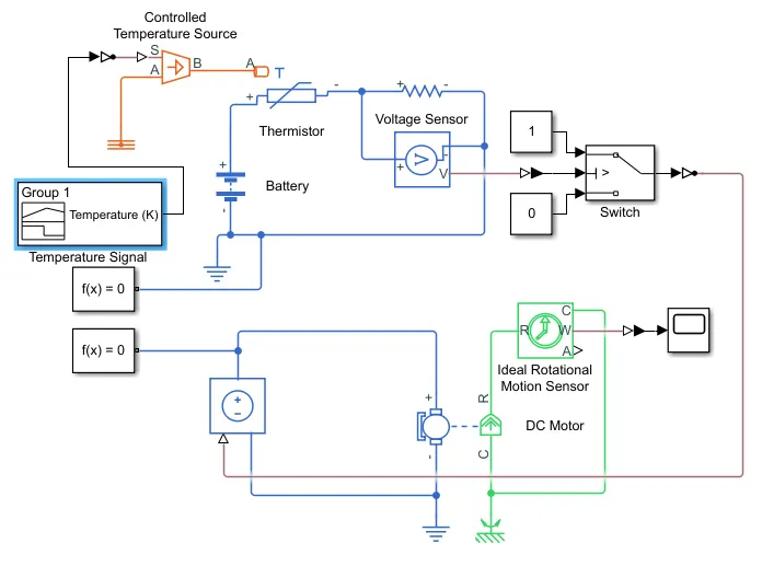
A signal builder block is used to generate three temperature signals
- 0-10 secs : 20 degree Celcius
- 10-30 secs : 27 degree Celcius
- 30-50 secs : 23 degree Celcius
The simulink signal is then converted into a physical signal and sent to a Controlled Temperature source block which generates a temperature equivalent to the input. The output from it is fed to an NTC (negative temperature co-efficient) thermistor block. A voltage sensor is placed across a resistor connected in series with the Thermistor. The entire circuit is energized by a 12V battery. The voltage sensor converts the voltage across the resistor into a physical signal proportional to the voltage and it is then converted into a simulink signal and passed via a Switch (wherein if the signal passes a threshold value only then will the switch be in in ON position i.e. 1, or else in OFF position i.e. 0). The simulink signal is converted into a physical signal and fed to a Controlled Voltage Source block which produces an equivalent voltage source and is fed to the D.C. Motor. An Ideal Rotational Motion Sensor is connected across the motor to observe the motion and a scope block is used to observe the output.
Blocks Used:
| Sl. No. | Symbol | Name of block | Function |
| i. |  |
Signal Builder | The Signal Builder block allows us to create interchangeable groups of piecewise linear signal sources and use them in a model. |
| ii. |  |
Controlled Temperature Source | The Controlled Temperature Source block represents an ideal source of thermal energy that is powerful enough to maintain specified temperature difference across the source regardless of the heat flow consumed by the system. |
| iii. |  |
Thermistor | The Thermistor block represents an NTC (negative temperature co-efficient) thermistor using the B-parameter equation. |
| iv. | |
Battery | This block models a battery. If we select Infinite for the Battery charge capacity parameter, the block models the battery as a series internal resistance and a constant voltage source. If we select Finite for the Battery charge capacity parameter, the block models the battery as a series internal resistance plus a charge-dependent voltage source. |
| v. | Resistor | The resistor block models a linear resistor. The voltage-current (V-I) relationship for a linear resistor is V=I*R, where R is the constant resistance in ohms. | |
| vi. |  |
Voltage Sensor | The Voltage Sensor block represents an ideal voltage sensor, that is, a device that converts voltage measured between two points of an electrical circuit into a physical signal proportional to the voltage. |
| vii. |  |
Switch | The Switch block passes through the first input or the third input signal based on the value of the second input. The first and third inputs are data input. The second input is a control input. |
| viii. |  |
Controlled Voltage Source | The Controlled Voltage Source block represents an ideal voltage source that is powerful enough to maintain the specified voltage at its output regardless of the current flowing through the source. |
| ix. |  |
D.C. Motor | The DC Motor block represents the electrical and torque characteristics of a DC motor. The parameters of the equivalent circuit of a D.C. motor can be defined within the model. |
| x. |  |
Ideal Rotational Motion Sensor | The Ideal Rotational Motion Sensor block represents an ideal mechanical rotational motion sensor, that is, a device that converts an across variable measured between two mechanical rotational nodes into a control signal proportional to angular velocity or angle. The initial angular position (offset) can be specified as a block parameter. |
| xi. | |
Scope | This block displays time-domain signals. It displays its input with respect to simulation time. It can have multiple axes (one per port); all axes have a common time range with independent y-axes. It allows us to adjust the time and the range of input values to be displayed. |
| xii. | |
Solver configuration | The Solver Configuration block specifies the solver parameters that a model needs before one can begin with simulation. |
| xiii. |  |
Thermal Reference | The Thermal Reference block represents a thermal reference point, that is, a point with an absolute zero temperature, with respect to which all the temperatures in the system are determined. |
| xiv. | Electrical Reference | The Electrical Reference block represents an electrical ground. Electrical conserving ports of all the blocks that are directly connected to the ground must be connected to an Electrical Reference block. | |
| xv. |  |
Mechanical Rotational Reference | The Mechanical Rotational Reference block represents a reference point, or frame, for all mechanical rotational ports. All rotational ports that are rigidly clamped to the frame (ground) must be connected to a Mechanical Rotational Reference block. |
| xvi. | |
PS-Simulink converter | The PS-Simulink Converter block converts a physical signal into a Simulink output signal. |
| xvii. | Simulink-PS converter | The Simulink-PS Converter block converts the input Simulink signal into a physical signal. |
Input Graph:
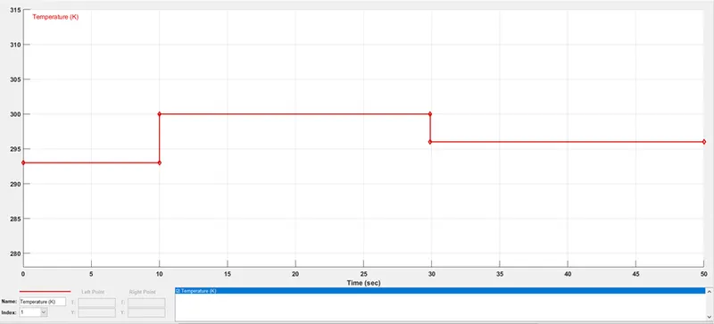
Here, the three temperatures i.e. 20 deg. Celcius, 27 deg. Celcius, 23 deg. Celcius is being converted into Kelvin i.e. 293 K, 300 K & 296 K due to the reference values in the Thermistor & Temperature controlled source being taken in Kelvin.
Output Graph:
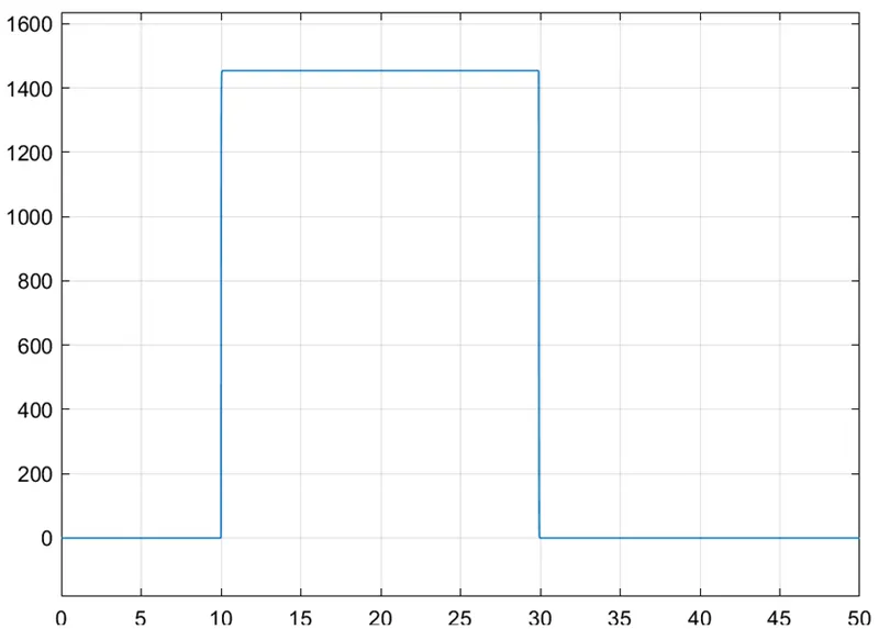
Observation:
From the output graph, we can see that during the first 10 seconds when the temperature input was 20 deg. Celcius / 293 K , the motor was not in operation. But, as soon as the input temperature rises above 25 deg. Celcius i.e. 27 deg. Celcius / 300 K, the motor starts operating and its speed output can be observed from the graph during the 10-30 seconds time interval. Again when the temperature falls down to 23 deg. Celcius / 296 K, it can be observed that the motor comes to a standstill.
CONCLUSION:
(from Doorbell Simulation)
After completing this simulation I have understood the modes of operation of a Solenoid (forward & backward motion), the purpose of an Ideal Translational Motion Sensor i.e. measurement of displacement (in this case) of the plunger.
(from Temperature Controlled Fan Simulation)
After completing this simulation I have understood how one can generate single & multiple signals with the help of a Signal Builder, the working of a Controlled Temperature Source, NTC Thermistor, Voltage sensor, Controlled Voltage source, D.C. motor, and an Ideal Rotational Motion Sensor.
Apart from all this, in general, one important thing must be taken care of, be it thermal, electrical or mechanical system, the reference blocks & solver configuration blocks are of utmost importance without which there will be no/erroneous(if any) output