Project 1 (Mini Project on Vehicle Direction Detection
MINI-PROJECT
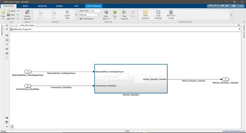
AIM: To create a model for Vehicle Direction determination
OBJECTIVE:
- Development of MATLAB Simulink model as per requirement.
- Tag the requirements to the Simulink model; tagging requirement 1 & requirement 2 to their corresponding subsystems is fine.
- MBD compliant changes, Data Dictionary creation & code generation is added advantage, and that is not the scope of this project.
- If choosing code generation, Storage class for Input signals: ImportedExtern; Storage class for Output signal: Export to File; Storage class for local signals: localizable; Storage class for calibration signals: Const.
- Choose sample time for all signals as 0.01s
REQUIREMENT 1:
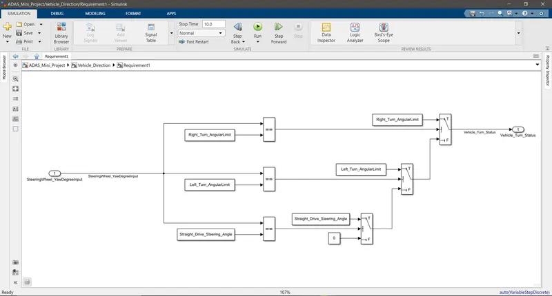
- Steering wheel input as yaw rate (Signal name: SteeringWheel_YawDegreeInput) is the input for this system.
- This is compared against 3 angular values, one each for left turn, right turn & straight drive (Calibration Values: Right_Turn_AngularLimit, Left_Turn_AngularLimit, Straight_Drive_Steering_Angle) to say which specific direction the steering wheel is turning towards.
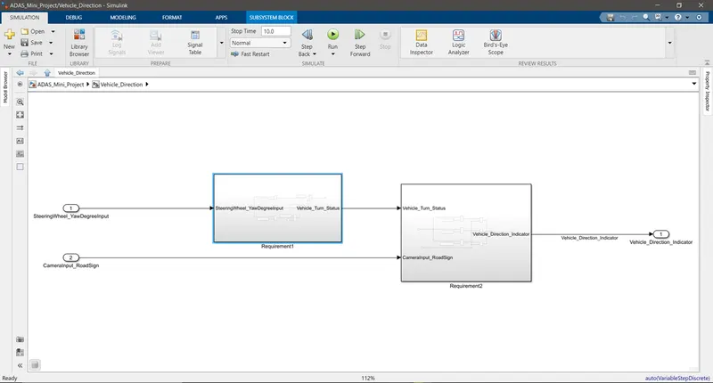
- Use switch blocks to compare & develop this requirement. Keep this requirement in a subsystem & output of this requirement is a local signal (Signal Name: Vehicle_Turn_Status).
REQUIREMENT 2:
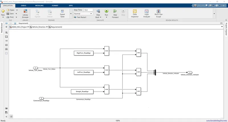
- Keep this requirement as a separate subsystem. Inputs to this requirement are local signal from requirement 1 (Signal Name: Vehicle_Turn_Status) & an input signal from camera (Signal Name: CameraInput_RoadSign), which confirms the occurrence of a road sign.
- Signal Vehicle_Turn_Status is compared against calibration values (Calibration Values: RightTurn_RoadSign, LeftTurn_RoadSign, Straight_RoadSign), if each of them is found equal, then each of the three corresponding output is compared against the camera input signal,
- Using a logical operator block, only one among them is finally given as output signal (Signal Name: Vehicle_Direction_Indicator).
SIGNAL & CALIBRATION DATA LIST:
|
Signal / Calibration Name |
Signal Type |
Data Type |
Dimension |
Min |
Max |
Initial Value |
Units |
|
SteeringWheel_YawDegreeInput |
Input |
Int16 |
1 |
-180 |
180 |
- |
Deg |
|
CameraInput_RoadSign |
Input |
Boolean |
1 |
0 |
1 |
- |
- |
|
Vehicle_Turn_Status |
Local |
Int16 |
1 |
-180 |
180 |
- |
Deg |
|
Right_Turn_AngularLimit |
Calibration |
Int16 |
[1 1] |
-180 |
180 |
30 |
Deg |
|
Left_Turn_AngularLimit |
Calibration |
Int16 |
[1 1] |
-180 |
180 |
-120 |
Deg |
|
Straight_Drive_Steering_Angle |
Calibration |
Int16 |
[1 1] |
-180 |
180 |
0 |
Deg |
|
RightTurn_RoadSign |
Calibration |
Int16 |
[1 1] |
-180 |
180 |
30 |
|
|
LeftTurn_RoadSign |
Calibration |
Int16 |
[1 1] |
-180 |
180 |
-120 |
|
|
Straight_RoadSign |
Calibration |
Int16 |
[1 1] |
-180 |
180 |
0 |
|
|
Vehicle_Direction_Indicator |
Output |
Boolean |
3 |
0 |
1 |
- |
- |
SIMULINK MODEL:
Main Model:
Subsystem Insight:
Requirement 1:
Requirement 2:
REQUIREMENT TAGGING:
The following are the step involved in tagging a requirement to a model:
1. Highlight the requirement stated in the Word File.
2. Right-click on the subsystem into which the particular requirement has to be tagged.
3. Select 'Requirements' and then select 'Link to Selection in Word'.
SLDD File:
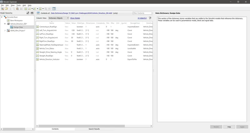
The signal & calibration data have been defined in the Simulink Data Dictionary as under and linked to the model.
MAB Guidelines Test in Model Advisor:
This test is done using the 'Model Advisor' option in Simulink to check whether the model meets the MAB standards.
Before you start with Model Advisor, one important check needs to be done, i.e. whether the Solver configuration is set to Fixed-Step & Discrete if not, it must be set and then the following are the steps to be followed:
1. Click on Model Advisor, a System selector window pops up.
2. Select the entire Model and then click ok.
3. After some time the Model Advisor window will open.
4. Navigate to 'Modeling standards for MAB' and then select the checkbox.
5. Now, click on 'Run Selected Checks'
6. Model Advisor will check the model and generate a report.
MAB Results:
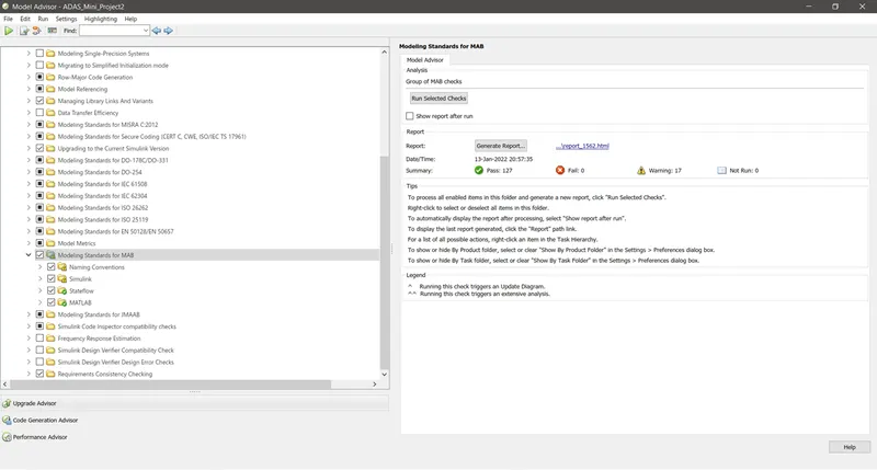
The entire report has been uploaded in .html format
C-Code Generation:
The following steps must be followed to Generate C-Code:
1. In the configuration block set the Solver to Fixed-step & Discrete, select step size, (I took 0.01)
2. Then under the Code Generation tab, change the System target file to 'ert.tlc' and check the Generate Code only checkbox and click on apply and ok.
3. From the apps section navigate to Embedded Coder.
4. C Code section opens up, select 'Generate Code'
Note: C-Code generation will be successful only if the MAB test has no Failures, else C-Code won't be generated.
/*
 * File: ADAS_Mini_Project2.c
 *
 * Code generated for Simulink model 'ADAS_Mini_Project2'.
 *
 * Model version                  : 1.16
 * Simulink Coder version         : 9.5 (R2021a) 14-Nov-2020
 * C/C++ source code generated on : Thu Jan 13 23:00:08 2022
 *
 * Target selection: ert.tlc
 * Embedded hardware selection: Intel->x86-64 (Windows64)
 * Code generation objectives: Unspecified
 * Validation result: Not run
 */

#include "ADAS_Mini_Project2.h"
#include "ADAS_Mini_Project2_private.h"

/* Real-time model */
static RT_MODEL_ADAS_Mini_Project2_T ADAS_Mini_Project2_M_;
RT_MODEL_ADAS_Mini_Project2_T *const ADAS_Mini_Project2_M =
  &ADAS_Mini_Project2_M_;

/* Model step function */
void ADAS_Mini_Project2_step(void)
{
  /* local block i/o variables */
  int16_T Vehicle_Turn_Status;
  real_T tmp_0;
  int32_T tmp;

  /* Switch: '<S2>/Switch' incorporates:
   *  Constant: '<S2>/Constant'
   *  Constant: '<S2>/Constant1'
   *  Constant: '<S2>/Constant2'
   *  Inport: '<Root>/SteeringWheel_YawDegreeInput'
   *  RelationalOperator: '<S2>/Relational Operator'
   *  RelationalOperator: '<S2>/Relational Operator1'
   *  RelationalOperator: '<S2>/Relational Operator2'
   *  Switch: '<S2>/Switch1'
   *  Switch: '<S2>/Switch2'
   */
  if (SteeringWheel_YawDegreeInput == Right_Turn_AngularLimit) {
    /* Switch: '<S2>/Switch' incorporates:
     *  Constant: '<S2>/Constant3'
     */
    Vehicle_Turn_Status = Right_Turn_AngularLimit;
  } else {
    if (SteeringWheel_YawDegreeInput == Left_Turn_AngularLimit) {
      /* Switch: '<S2>/Switch1' incorporates:
       *  Constant: '<S2>/Constant4'
       */
      tmp_0 = (real_T)Left_Turn_AngularLimit * 0.015625;
    } else if (SteeringWheel_YawDegreeInput == Straight_Drive_Steering_Angle) {
      /* Switch: '<S2>/Switch2' incorporates:
       *  Constant: '<S2>/Constant5'
       *  Switch: '<S2>/Switch1'
       */
      tmp_0 = (real_T)Straight_Drive_Steering_Angle * 0.015625;
    } else {
      /* Switch: '<S2>/Switch1' incorporates:
       *  Constant: '<S2>/Constant6'
       *  Switch: '<S2>/Switch2'
       */
      tmp_0 = 0.0;
    }

    tmp = (int32_T)fmod((int32_T)floor(tmp_0 * 64.0), 65536.0);

    /* Switch: '<S2>/Switch' incorporates:
     *  Constant: '<S2>/Constant2'
     *  RelationalOperator: '<S2>/Relational Operator2'
     *  Switch: '<S2>/Switch1'
     *  Switch: '<S2>/Switch2'
     */
    Vehicle_Turn_Status = (int16_T)(tmp < 0 ? (int32_T)(int16_T)-(int16_T)
      (uint16_T)-(real_T)tmp : (int32_T)(int16_T)tmp);
  }

  /* End of Switch: '<S2>/Switch' */

  /* SignalConversion: '<S3>/Signal Conversion' incorporates:
   *  Constant: '<S3>/Constant'
   *  Constant: '<S3>/Constant1'
   *  Constant: '<S3>/Constant2'
   *  Inport: '<Root>/CameraInput_RoadSign'
   *  Logic: '<S3>/Logical Operator'
   *  Logic: '<S3>/Logical Operator1'
   *  Logic: '<S3>/Logical Operator2'
   *  RelationalOperator: '<S3>/Relational Operator'
   *  RelationalOperator: '<S3>/Relational Operator1'
   *  RelationalOperator: '<S3>/Relational Operator2'
   *  Switch: '<S2>/Switch'
   */
  Vehicle_Direction_Indicator[0] = ((Vehicle_Turn_Status == RightTurn_RoadSign) &&
    CameraInput_RoadSign);
  Vehicle_Direction_Indicator[1] = ((Vehicle_Turn_Status == LeftTurn_RoadSign) &&
    CameraInput_RoadSign);
  Vehicle_Direction_Indicator[2] = ((Vehicle_Turn_Status == Straight_RoadSign) &&
    CameraInput_RoadSign);
}

/* Model initialize function */
void ADAS_Mini_Project2_initialize(void)
{
  /* (no initialization code required) */
}

/* Model terminate function */
void ADAS_Mini_Project2_terminate(void)
{
  /* (no terminate code required) */
}

/*
 * File trailer for generated code.
 *
 * [EOF]
 */
CONCLUSION:
After completing this mini project I have learned to create Complex Simulink models, signal labeling, resolving of signals, testing a model for MAB, generation of MAB report.