Week -2
1) DOORBELL CHALLENGE:
AIM: To make a simulink model of doorbell model using solenoid block and to obeserve the physical movement of the plunger.
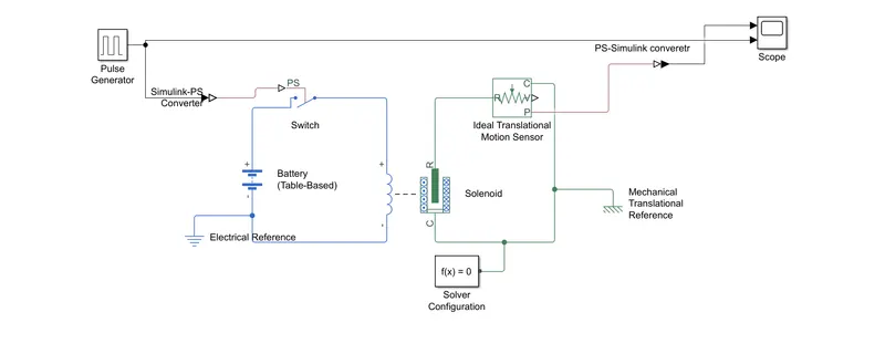
MODEL: The simulink model of the required challenge is shown below.
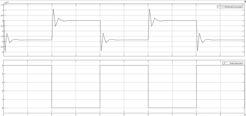
WAVEFORM: The waveform of the door bell model is shown below.
EXPLANATION:
- First, we considerd a pulse genertor(here, amplitude 5) and values were given as shown in the waveform.
- Then it is connected to Simlink-PS converter as it converts the simulink into physical signal.
- The signal from Simulink-PS converter was given to a physical signal switch.
- A battery(Of any value) was connected acroos an inductor which is electically connected to solenoid and a reference (Electrical) was connected to both.
- An ideal translatonal motion sensor was connected from terminal 'R' of solenoid. 'C' terminal of both sensor and solenoid block was connetced to reference (Mechanical).
- A solver configuration block was connected to each physical single network (Here only one).
- Then signal from sensor block was connected to PS-simulink converter and then given to scope.
RESULT:
The result of the model was shown in the waveform above. From the waveform, it was observed that
- From 0 to 2 sec, pulse genertor was in "ON" condition. Duringt this time, energy was absorbed from the source.
- From 2 to 4 sec, pulse generator was in "OFF" condition.During this time, energy was released to the source and it was repeated continously.
,
2)THERMISTOR CHALLENGE:
Use a thermistor to sense the temperature of a heater & turn on or turn off the fan as per below conditions:
Temperature source: 20 °C from 0 to 10 seconds,
27 °C from 10 to 30 seconds,
23 °C from 30 to 50 seconds.
Fan conditions: ON if the temperature above 25 °C, OFF otherwise.
AIM: To make simulink model of the thermistor according to given conditions.
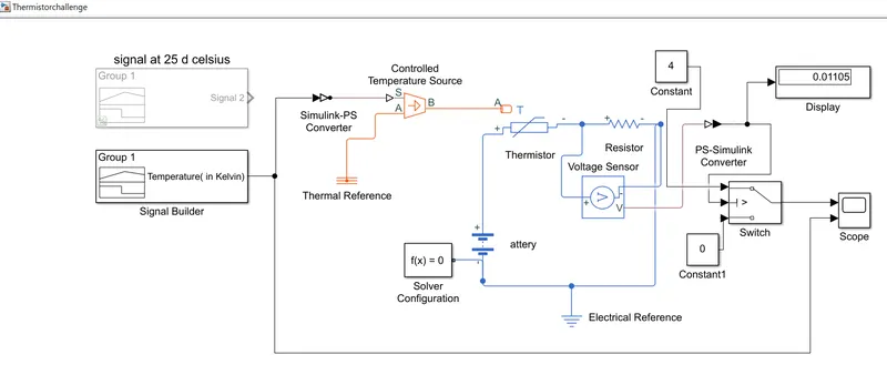
MODEL:
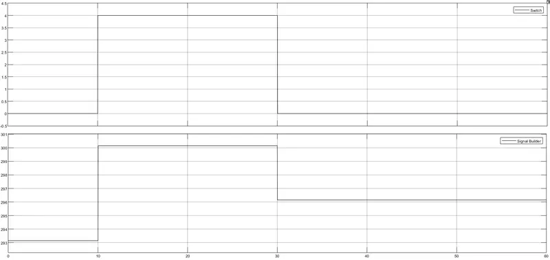
WAVEFORM: The waveform of the thermistor model is shown below.
EXPLANATION:
- All the blocks were connected as shwon in the model.
- In signal builder block, all the values were gievn in "Kelvin" as all the thermal blocks will be in "Kelvin" by default (0 degree celsius= 273.15 Kelvin).
- To get voltage at 25 degree clesius, we have created another signal builder block and value is noted.
- That value is given as threshold value in switch block.
- Then we have given that if given condition is satisfied, the signal has to pass through the constant block( magnitude 4) and that is the our required output.
RESULT:
From the waveform, it is oberved that
- The fan is in "ON" condition during the interval of 10 to 30 sec and "OFF" for rest of the interval.