Week -2
AIM:
- To make a Simulink model of a door bell using solenoid block.
- To use a thermistor to sense the temperature of a heater and turn ON and turn OFF the fan.
OBJECTIVE OF THE PROJECT:
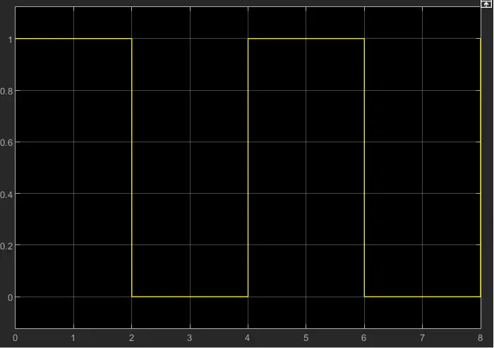
- To create a situation where the switch is closed for 2 seconds and then released and observe the physical movement of the plunger.
- To use a thermistor to sense the temperature of a heater & turn on or turn off the fan as per below conditions:
Temperature source: 20 °C from 0 to 10 seconds, 27 °C from 10 to 30 seconds, 23 °C from 30 to 50 seconds
Fan conditions: ON if the temperature above 25 °C, OFF otherwise.
BODY OF CONTENT:
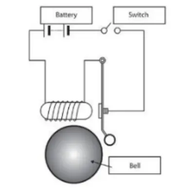
Model diagram of a doorbell setup:
Simulink model of a door bell using solenoid block:
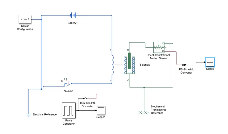
Explanation:
Required blocks from the library:
- Battery
- Switch
- Pulse generator
- Simulink-PS converter
- Solenoid
- Electrical reference
- Ideal motion translational sensor
- Mechanical translational reference
- Scope
- PS-Simulink converter
Solenoid:
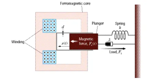
It is one of the varieties of transducer devices that convert energy into linear motion. In simple terms, a solenoid converts electrical energy into mechanical work. The term is also often used to refer to a solenoid valve, an integrated device containing an electromechanical solenoid which actuates either a pneumatic or hydraulic valve, or a solenoid switch, which is a specific type of relay that internally uses an electromechanical solenoid to operate an electrical switch.
Circuit connection:
Solenoid is connected to battery and switch with pulse generator which is the input device. The pulse generator which is the SIMULINK block in order to connect to the SIMSCAPE block Simulink-PS converter is used. Scope displays the result of the input and output values.
Electrical and mechanical translational reference are connected to the electrical and mechanical circuit which acts as reference to the system.
The other ends of the solenoid are connected to the ideal translational motion sensor. The results of the sensor are displayed in the scope which is simulink block. So, PS-Simulink converter is used to connect ideal translational motion sensor and scope.
Pulse generator input parameters:
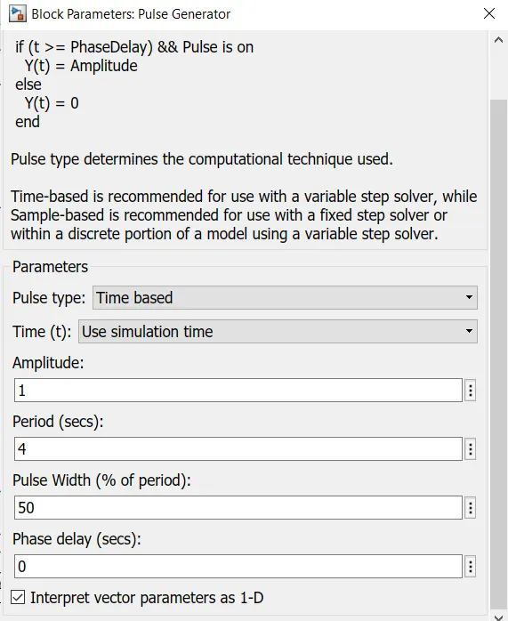
As per the requirement, the switch should be closed for 2 seconds and then released. So, the input parameters in the pulse generator have to be modified where the pulse width is given as 50% and period is entered as 4 seconds. By doing so, for 4 seconds the switch is on for 2 seconds and closed for remaining 2 seconds. Then this pulse pattern is repeated.
RESULT:
CONCLUSION:
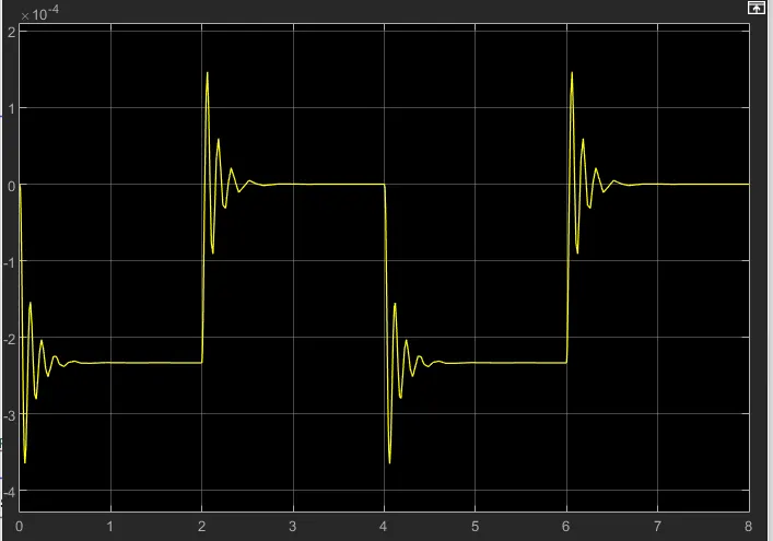
When switch is ON, the circuit is closed and the current flows from the battery to the circuit where the bell rings for 2 seconds and stopped as per the input given in the pulse generator (50% Pulse width for time period of 4 seconds) by the action of solenoid that vibrates as the current is passed.
Then physical movement of plunger is observed by the translational motion sensor and its result is displayed in the scope through the PS-Simulink converter. By reducing the spring constant value and increasing the damping value the vibrations is reduced.
SENSING THE TEMPERATURE OF THE HEATER USING THERMISTOR
Thermistor:
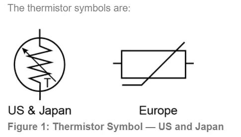
A thermistor is a resistance thermometer, or a resistor whose resistance is dependent on temperature. The term is a combination of “thermal” and “resistor”. It is made of metallic oxides, pressed into a bead, disk, or cylindrical shape and then encapsulated with an impermeable material such as epoxy or glass.
There are two types of thermistors: Negative Temperature Coefficient (NTC) and Positive Temperature Coefficient (PTC). With an NTC thermistor, when the temperature increases, resistance decreases. Conversely, when temperature decreases, resistance increases. This type of thermistor is used the most.
A PTC thermistor works a little differently. When temperature increases, the resistance increases, and when temperature decreases, resistance decreases. This type of thermistor is generally used as a fuse.
Typically, a thermistor achieves high precision within a limited temperature range of about 50ºC around the target temperature. This range is dependent on the base resistance.
Circuit diagram of thermistor:
Requirement:
To use a thermistor to sense the temperature of a heater & turn on or turn off the fan as per below conditions:
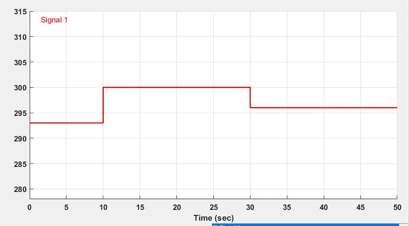
Temperature source: 20 °C from 0 to 10 seconds, 27 °C from 10 to 30 seconds, 23 °C from 30 to 50 seconds
Fan conditions: ON if the temperature above 25 °C, OFF otherwise.
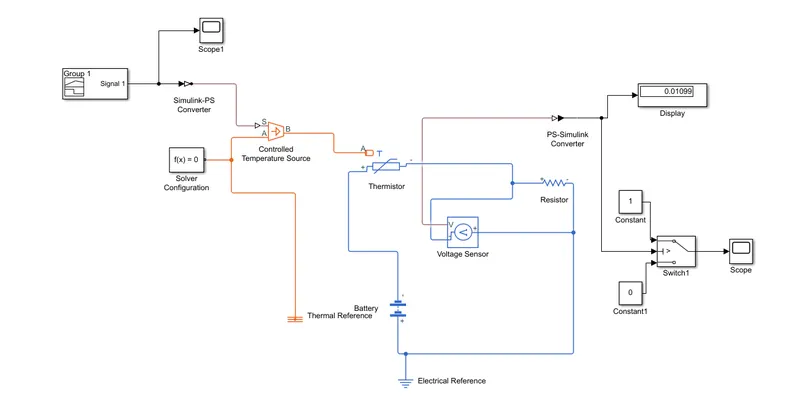
Circuit model of the requirement in SIMULINK:
Required blocks from library:
- Signal builder
- Scope
- Simulink-PS converter
- Controlled temperature source
- Thermistor
- Battery
- Thermal reference
- Electrical reference
- Solver configuration
- Voltage sensor
- Resistor
- PS-Simulink converter
- Switch
- Constant
- Display
Signal builder:
Signal builder is used to give inputs to the system which displays time in seconds in X-axis and temperature in Kelvin in Y-axis. Since the values of temperature is given in Kelvin to the thermistor, it can take values in Kelvin only. As per the requirements given in question, the values of temperature are adjusted with respect to time in signal builder. In axes option, the time range is changed to 50 seconds.
Controlled temperature source:
This block represents an ideal energy source in a thermal network that can maintain a controlled temperature difference regardless of the heat flow rate. The temperature difference is set by the physical signal port S. A positive temperature difference causes the temperature at port B to be greater than the temperature at port A.
Circuit connection:
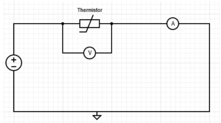
The signal builder is connected to the controlled temperature source through the Simulink-PS converter since signal builder is a simulink block. Then the controlled temperature source is connected to the thermistor through the port ‘A’ and the other terminals of the thermistors are connected to the battery, resistor and voltage sensor which shows temperature values in volts and threshold value is calculated for the required temperature.
Circuit for thershold calculation:
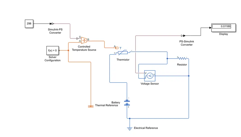
The temperature range for which the fan should ON is 25°C. So, the threshold value for 298 K is calculated. From the above connection. The value is found to be 0.01189. this value is entered to the switch as a threshold value.
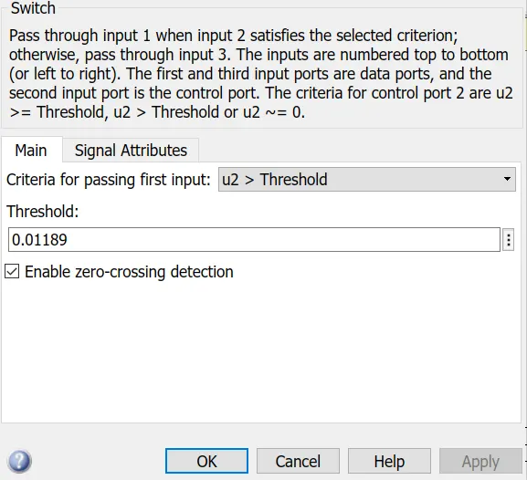
Then switch is connected to the circuit with 2 constant blocks (1 & 0) representing ON and OFF.
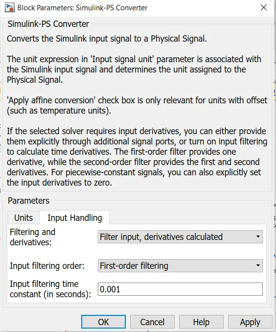
Then, in the PS-Simulink converter, filtering and derivatives option is made ON and then the simulation is performed.
RESULTS:
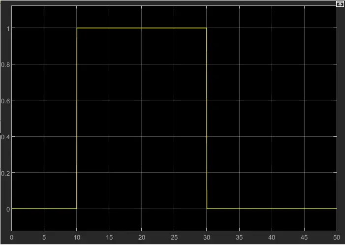
For the first 10 seconds and for the last 30 seconds, since the temperature is less than 25°C the amplitude result shows ‘0’ which indicates that the fan is switched OFF. From 10 to 30 seconds, the fan is switched ‘ON’ since the amplitude shows value '1'.
CONCLUSION:
- Thus, a Simulink model of a door bell using solenoid block is created where the switch is closed for 2 seconds and then released.
- A thermistor is modeled to sense the temperature of a heater and turn ON when the temperature rises up above 25°C and turn OFF the fan when the temperature falls below the range using Simulink.