Week -2
Q1. Make a Simulink model of Doorbell using solenoid block with the following details:
In the above arrangement, when the switch is closed the electromagnet receives electrical power from the battery and pulls the metal arm to hit the bell producing sound.
Create a situation where the switch is closed for 2 seconds and then released. Observe the physical movement of the plunger.
Assume remaining parameters
ANSWER 1:
OBJECTIVE:
Create a Simulink Model for a doorbell using Solenoid Block.
Make the switch to Open and Close for 2 second
see the physical movement of the plunger.
SIMULINK MODEL:
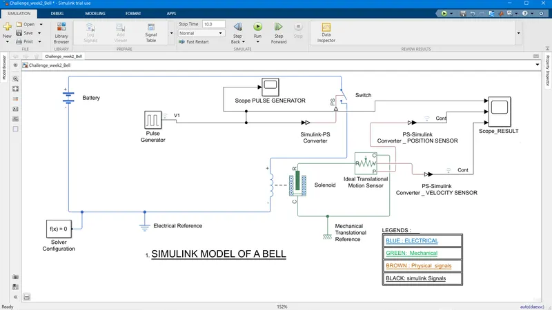
DESCRIPTION:
To create the model of a Bell, I used a battery, a switch and Solenoid model from the Simscape Electrical library.The Switch is a Single Pole Single Throw ( SPST) switch taken from the switch and breaker section. The battery is taken from the source section and the solenoid model is from the Mechatronics actuator under Electromechanical Section.
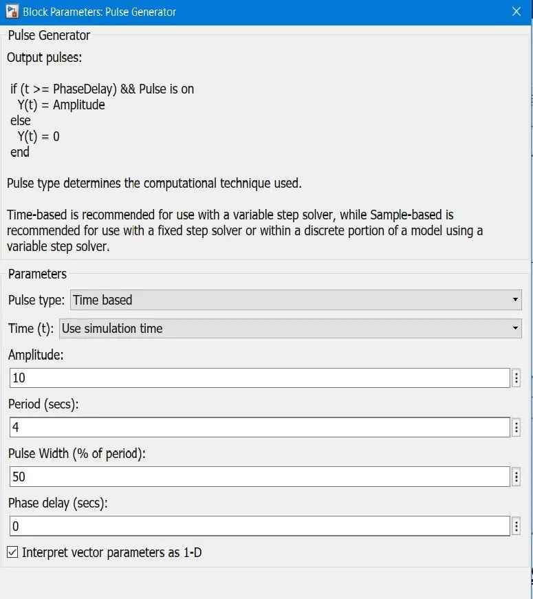
To make the switch close for two second and open, I used a Pulse generator and configured the parameter of the pulse generator to open and close every two second.
Since the switch is a physical model, and the Pulse generator is a Simulink model, We need to interphase the pulse generator and the switch using a Simulink to PS convertor as shown in the drawing.
The solenoid is modeled as the bell. once the switch is on, the solenoid will get activated and cause the plunger to move.
To observe the movement of the plunger, I have used a ideal translational motion sensor, as the movement of the plunger is linear.
we can observe the out put of the ideal translational motion sensor byy connecting it to a scope, while interphasing the physical and simulink signals using a PS to Simulink Convertor as shown in the diagram.
The Question required to observe the Position of the Plunger, However I added to the Velocity output as well to compare the velocity.
Since the simulink model has two physical system, Electrical and Mechanical. The model requires two References.For that, I have added an Electrical Reference and a Mechanical Translational Reference from the Simscape Foundation library.
Simscape requires a Solver function to carry out the simulation as it generates all the governing equation by itself. Therefore a Solver Configuration is added.
Finally The Simulation stop time is set for 10 second and the Results Observed.
RESULTS
Below are the Results of the Simulation
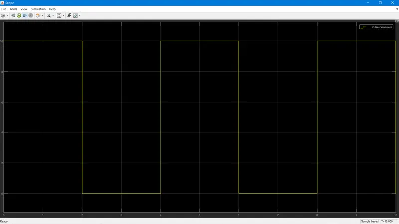
1. Out put of the Pulse Generator with time period of 4 second, keeping the switch open for 2 second and closed for 2 second.
The Output of the Ideal Translational Motion Sensor along with the output of the pulse generator
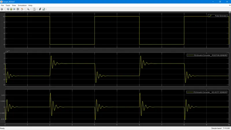
The Ideal Translational Motion Sensor parameter unit was changed from m to cm to get a better observation.
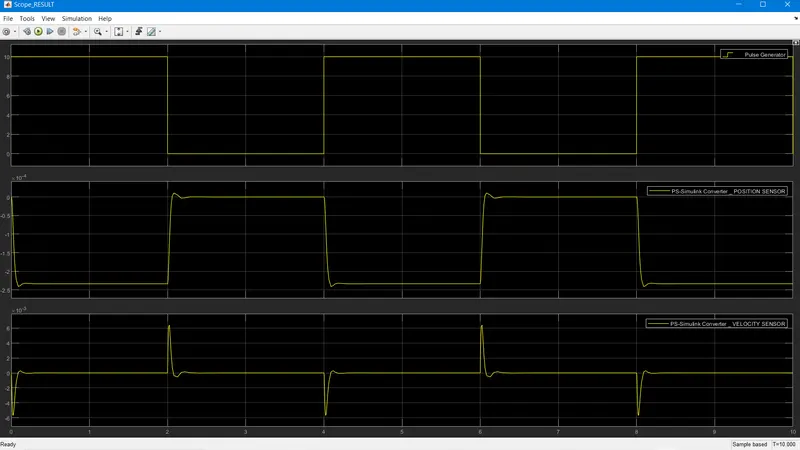
The top graph is the output of the Pulse generator, the middle graph is the position output of the Plunger and the bottom graph is the velocity profile of the plunger as it moves.
OBSERVATION
It could be observed that once the switch closes the plunger moves about 2.2 cm and holds till the switch doesnt open again.once it opens it goes back to the zero position. it could be observed that there is a transcient of about .5 second in the motion of the plunger, during opening and closing of the switch, indicating less damping. we can reduce this, if we need by increasing the damping parameter of the solenoid from 1 to 5 in the mechanical settings of the solenoid.
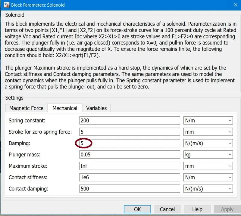
Below is the output while setting the damping of the solenoid to 5.
Q 2 Use a thermistor to sense the temperature of a heater & turn on or turn off the fan as per below conditions:
Temperature source: 20 °C from 0 to 10 seconds, 27 °C from 10 to 30 seconds, 23 °C from 30 to 50 seconds
Fan conditions: ON if the temperature above 25 °C, OFF otherwise.
ANSWER #2
OBJECTIVE:
Build a Temperature sensing device using a Thermister and Start and Stop a Fan according to the following conditions.
Temperature source: 20 °C from 0 to 10 seconds, 27 °C from 10 to 30 seconds, 23 °C from 30 to 50 seconds
Fan conditions: ON if the temperature is above 25 °C, OFF otherwise.
SIMULINK MODEL
DESCRIPTION:
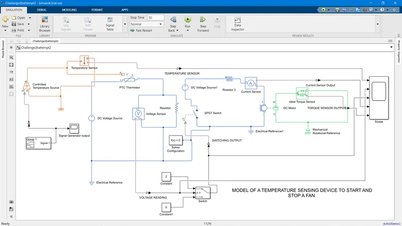
The model consist of three sections which uses three different types of Simscape Blocks. 1) Thermal Section 2) Electrical Section and Mechanical Section. Then these three models are interphased together to get the result.
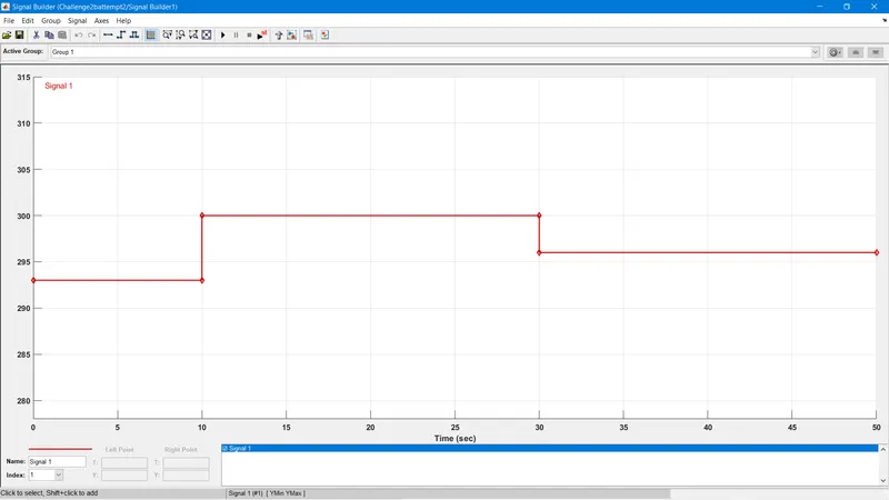
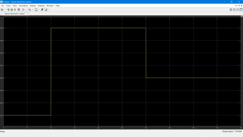
To get the required temperature An Ideal Controlled Temperature Source was used, whose temperature setting was given according to the temperature requirement. This was achieved by generating a Signal using Signal denerator whose specific were given as per the Temperature requirements.
The Temperature profile is shown below.The initial Temperature is given as 293.15 K which is equal to 20 C for the first 10 sec. and then 300.15 K ( 27 C) till 30 Second. and then to 296.15 K ( 23C) from 30 to 50 Sec.
The signal output on a Scope.
The temperature source provide the required temperature to the Thermister. The temperature is also recorded using a Temperature sensor.
The Thermister is a Resister whose resistance varies with temperture. A PTC Thermister has a Positive Temperature co-efficient, which means its resistance increases with the temperture.
The Thermister is connected with a resistor in series, across which a Voltage sensor is connected.As the Resistance in the Thermister varies, the Voltage across the Resistor also changes. This change in voltage is used operate a switch whose threshold value is set based on the voltage and temperature settings. Ther threshold value is set to 0.01, which means if the threshold value increases more than 0.01, the swich would change its position. two setting are given.
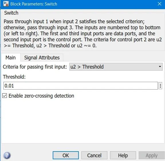
Two Constant block of two and zero was used to give the fan operating condition.2 stand for starting the fan and 0 for switching off the fan.The output of the Switch is connected to another SPST ( Single Pole Single throw) switch which runs a DC motor using a DC voltage source.
When the Selector switch is in Position 2. the SPST will close, completing the circuit and starting the DC motor and running the fan and when the Selection is at Zero the SPST opens and The DC motor is Stopped. The opening and Closing of the SPST can be observed using a Current Sensor which is connected in Series with the DC motor.
To detect the Running of DC motor a Ideal Torque Sensor is used.
The Output of the Temperature sensor, voltage sensor, Output of the Selector Switch , Current sensor, and the Ideal torque sensor is put on a scope to see the result.
The model was simulated for 50 Sec to see the output.
RESULT :
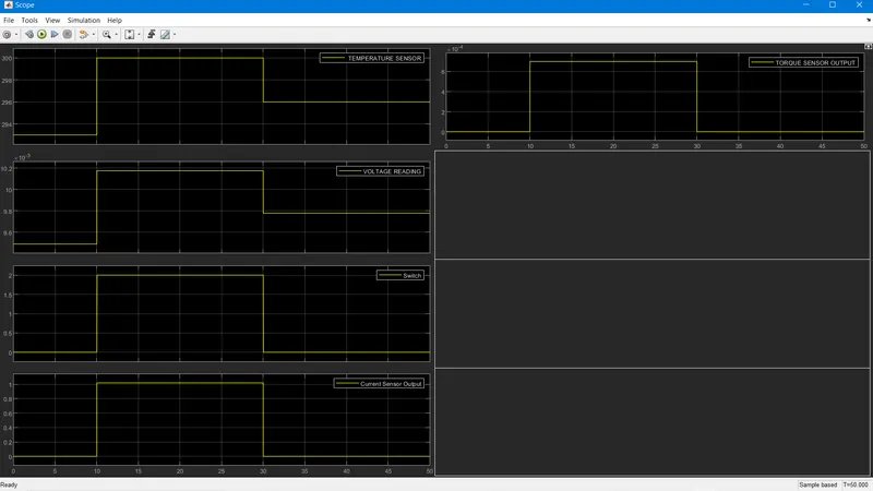
There are 5 output in the scope.
The first one is the Temperature Sensor. which shows the temperture output was according to the requirement of the System. ( 20C from 0 to 10 sec, 27 C from 10 to 30 Sec, and 26 C from 30 to 50 Sec).
The second reading from the scope is that of the Voltage Sensor. the voltage out put is similar to the Temperature output showing the relationship of thermister with temperature.
In the Third reading of the scope which shows the output of the Selector switch; it could be seen the the switch changes to 2 when the temperature increases more than 25 and temperature drops below 25 C ( based on the threshold value)
In the forth scope the SPST Switch is operating correctly can be seen by the Current sensor output as current is detected when the Selector switch changes position to 2 and Current falls to zero when Selector switch changes back to Zero.
Finally we can see torque detection from 10 to 30 second when the Swich is on, indicating the Motor is running when the temperature is greater than 25 and stops when the temperature is less than 25.