Week - 4
- Implement control logic of a “washing machine” using Stateflow as per given sequence:
- If the power supply is available, the system gets activated
- If the Water supply is not available, stop the process & indicate through LED
- Soaking time should be 200s followed by Washing time of 100s.
- Then rinsing happens for next 20s & dryer runs for 50s
ANSWER :
SIMULINK AND STATE FLOW LOGIC MODEL
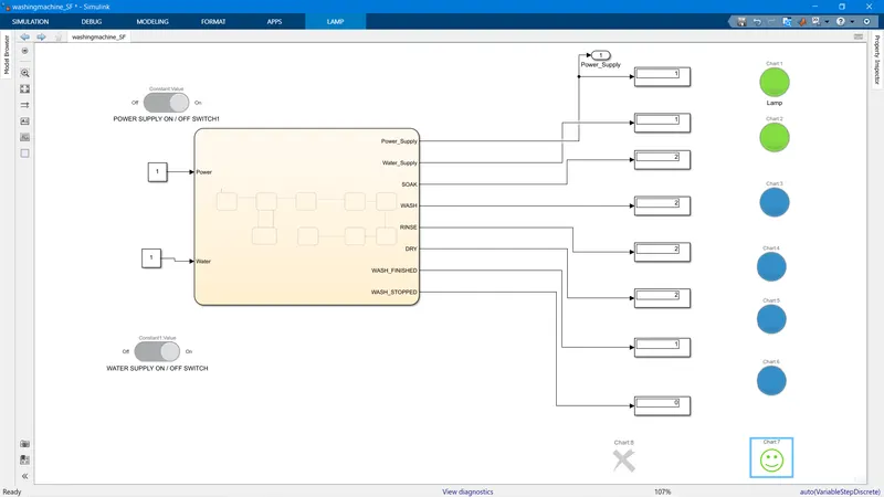
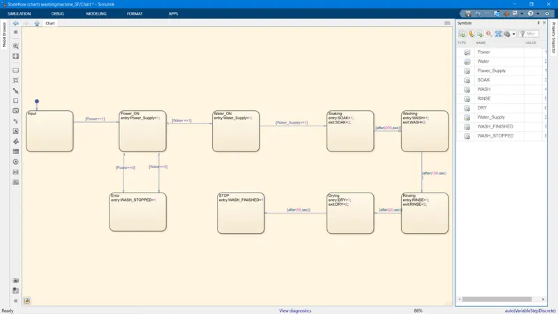
The Simulink and State flow model is shown above.
DISCRIPTION:
The Washing machine model has two input
1) Power Supply
2) Water Supply
These two were denoted by a Contant Block with a selector switch from the dashboard to give ON/ OFF Condition.
Inside the State flow chart, Input Power and Water was assigned to give Start the Process.
Several other States was assigned; POWER_ON, WATER_ON,SOAKING, WASHING, RINSING, DRYING , STOP and ERROR. These are States inside the Stateflow chart, showing diffrent states in the State flow logic, showing different stages of the Washing process.
For Each State, an output variable was assigned to indicate in which state is the Washing Process.
Power_Supply, Water_Supply,SOAK, WASH, RINSE,DRY and WASH_STOP and WASH_FINISHED are the output variable.
each variable become active when the state is entered,this is given by the command entry, For example ( entry:SOAK=1) informing SOAKING is going ON and gives an out value of 1.when the State leaves,the "exit" command is used to change the output to two. eg: (exit:SOAK=2) indicating Soaking is over.
From moving from one state to another conditions are given.In this model there are two type of conditions, Condition checking and Time delay.
The Power Supply and Water Supply should be active to Start Washing Process. there fore there require condition Checking.
Once the Process starts, Then the rest of the condition follow time delay in sec.once the time elapses, it moves to the next condition.
These two are achived by checking condition command (==) and time delay command after( time,sec) command.
These command are checked in between the "States".
For eg: to check the Water Supply is available, Water_Supply==1 condition is checked if it is true only then the Stateflow enters the Soaking State. Incase the Water_Supply==0, It will go to the "error state" and Wash_Stop indication will show.
once inside the Soaking State, the Soaking Begins, and only after 200s as defined by the condition "after(200,sec) does the State flow leaves the Soaking State.and once it leaves the Soaking State the exit command stops the soaking contion.
This process continues, following the condition till it reaches the end.
To illustrate the condition. outside the State flow chart, Lamps are used to show different Stages of the State flow condition. the LED shows GREEN when the state is active and RED when the State is inactive and the BLUE lamp is used to indicate that process is done.
The Error indication is Shown with a Cross Symbol and "The SMILEY " shows the Process complete.
The Model was Simulated for 500 Sec to see the results.
RESULT
When the power supply is ON and Water Supply is ON.
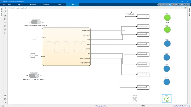
The Green Lamp indicate the Power Supply and Water Supply is ON, and The Blue Lamp indicate each step is done and finally The Washing Done Step is shown in the SMILEY Turned Green.
Condition 2: When the Water Supply is OFF.
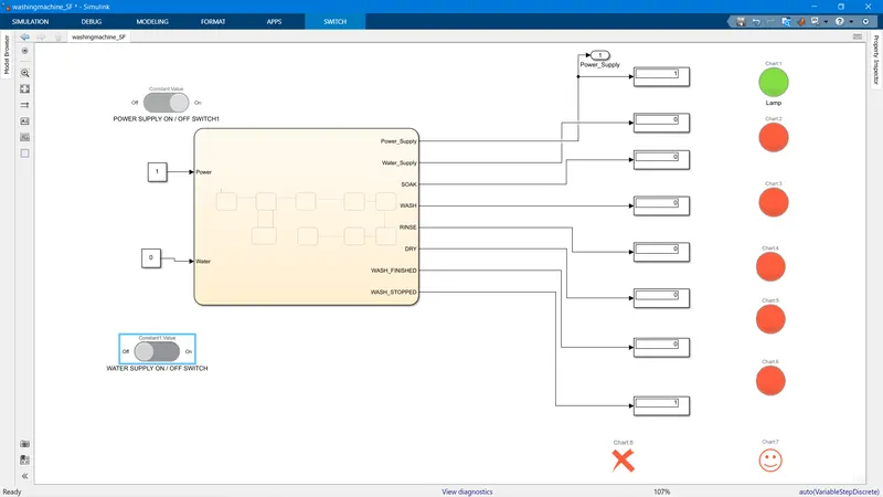
It can be seen only the Power Supply Lamp is Green and the rest of the Lamp is Red, indicating the Washing is not done. The Cross Indication has turned RED, Showing its active, and there is an Error.
Condition 3: When Power Supply is not On and the water Supply is ON.
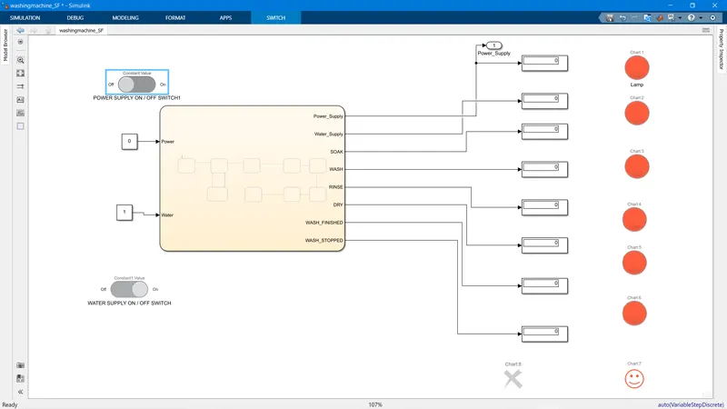
This Result shows the System is Inactive, as None of the LED turned ON, All the LED are Red showing Inactive, and The Error Indication is also Not ON. Even though the water Supply is ON, it doesnt get turned ON, as There is no Power Supply.
Q2.
2. Make a Simulink chart for the “Gear shift” logic as per below conditions:
Speed Range(kmph) Gear
0 to 15 1
16 to 25 2
26 to 40 3
41 to 60 4
Above 61 5
Give speed input while the simulation is running & display the gear number.
ANSWER 2:
SIMULINK AND STATEFLOW MODEL
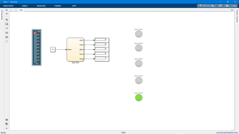
SIMULINK MODEL
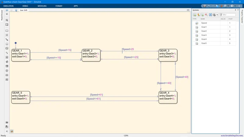
STATEFLOW MODEL
DISCRIPTION
The Gear Model Uses a Vertical Slider to Adjust the speed. The Slider is connected to constant block which is the input of the gear Stateflow chart.
The State flow has One Input Speed, and 5 output state, Gear Numbers 1,2,3,4,5 are the Output variable.
There are 5 states to show the 5 gears Position and gear out put are connected to a Display to show the output and to a lamp, which turns green when active.
The States are assigned active when entered, and in active when exited, this is done by (entry: GEAR 1=1; and exit: GEAR 1 = 0)
The change in state is decided by the Speed Logic condition shown on the arrow.
The simulation is done for infinite time, and the Speed is change using the slider to see the gear output.
RESULT
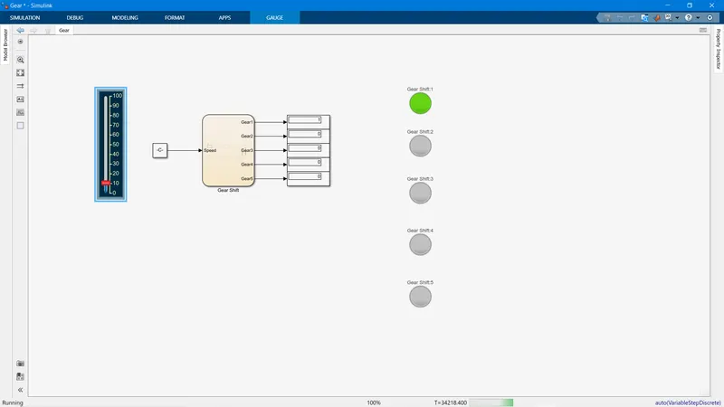
Speed =10 results in GEAR 1.
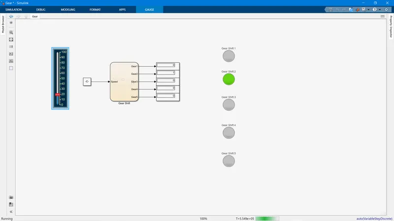
Speed 20 ; Gear out put 2.
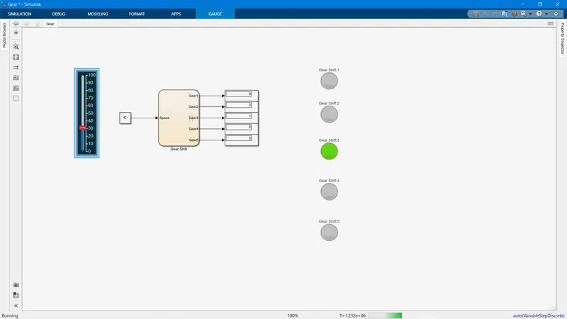
Speed 30; GEAR output =3
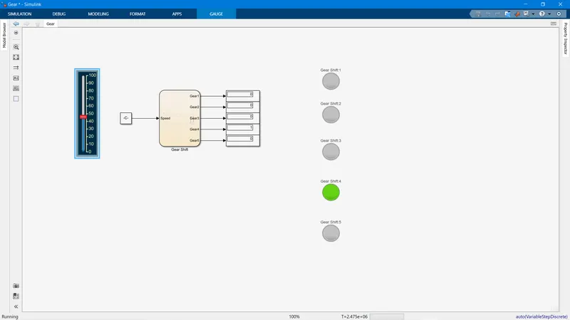
Speed = 47, Gear output is 4
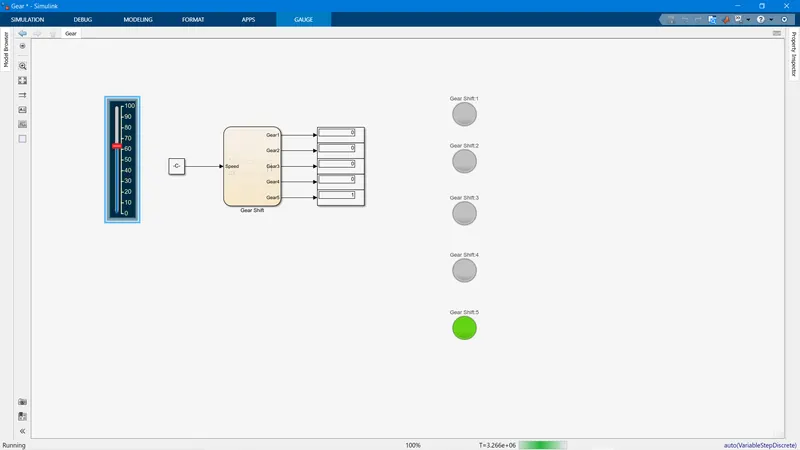
Speed = 64 ; Gear Output = 5.
As the speed is changed in the slider, the Gear position also changes according to the condition.