Week-7 Challenge: DC Motor Control
1. A. Explain a MATLAB demo model named ‘Speed control of a DC motor using BJT H-bridge’.
B. Comment on the armature current shoot-up from the scope results.
C. Refer to the help section of ‘The Four-Quadrant Chopper DC Drive (DC7) block’. Compare it with the H-bridge model.
Answer:
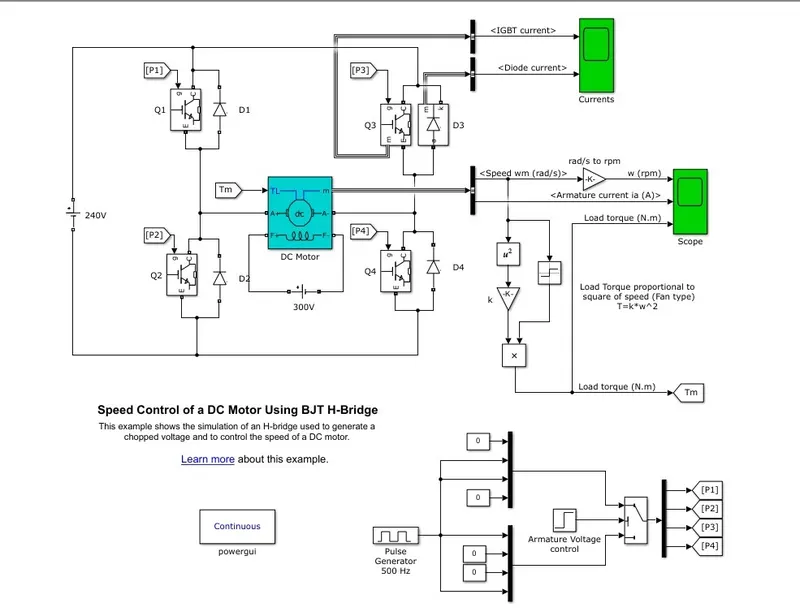
The MATLAB demo model " Speed control of a DC motor using a BJT H- Bridge is shown Below"
To explain the Model, first lets us look at a H bridge circuit.
A H bridge is a simple circuit which allows us to control a DC motor to operate in the forward and reverse direction.
It consist of 4 switching device, with the load in the center in the form of an H.
for eg:
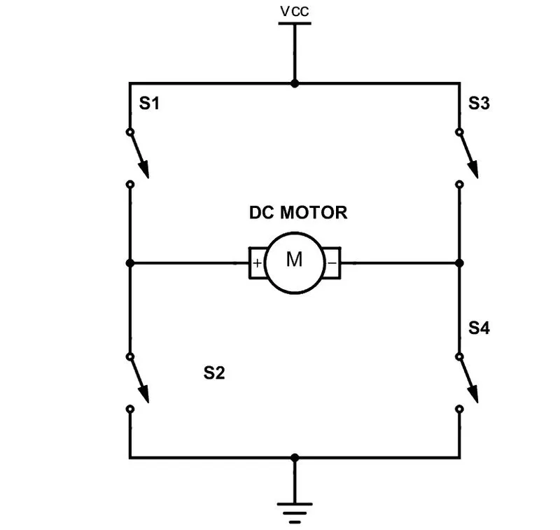
The motor can be rotated in the forward or reverse direction depending on which switches are opened and closed.
In the Matlab model, Q1, Q2, Q3, Q4 are the switches, and DC motor is the load.
In General When Q1, and Q4 are On the Motor will move in the Forward direction and when Q2 and Q3 are one the motor will move in the reverse direction. Never should Q1, and Q2 or Q3 and Q4 should be started together, as this will cause a short circuit and burn the diodes.
In the Matlab model, IGBT model are used as the Switching device. The source voltage is 240 V and The DC motor is given a field voltage of 300 V. For a Fan type model whose speed torque characteristics is T = k`omega square`, a simulink block model is done.
4 diodes are attached in Parallel to the switches, D1,D2,D3,D4.
These are Catch diodes, to ensure the protection of the circuit during switching action.
The control of the switching action is given by a simulink pulse generator with a duty cycle of 75 % given a voltage of 180 V and amplitude of 1. The switching takes place in half sec.
The IGBT current and Diode current are shown in a scope.
While the motor paratemers, Speed, armeture current and load torque are shown in another scope. the Load Torque is proportional the square of the speed.
when we simulate the model for 1 sec.
The following output comes
1. The IGBT and Diode current are shown below.
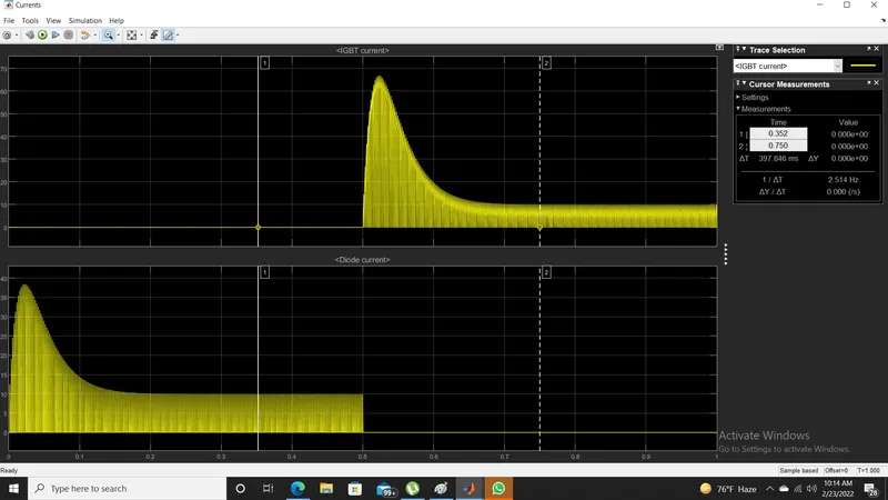
There is a peak current during the swiching of the devices which then comes to a steady state.
At the time of switching current in IGBT goes to about 65 and drops to 10 ,and Diode current goes to 35 and drops to 10 in steady state respectively.
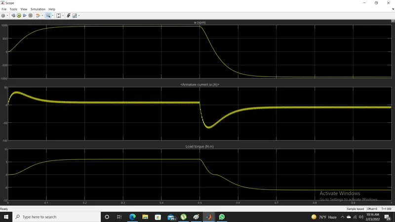
2. The speed armeture and load torque are shown below.
Q1 B
Generally the armature current of a DC motor shoots up during starting because the armature resistance is low, therefore high current flows through it. the starting current can be controlled by a resistance.
In this model a load is modeled as a fan, where Load torque is proportional to square of speed.
During starting, the speed and torque is less, thus high current flows through the armature due to low armature resistance. As the speed and torque increases, the current drops.
To further reduce the starting current a Series resistance can be added.
Answer 2:
A 2 Quadrant Chopper model is created below
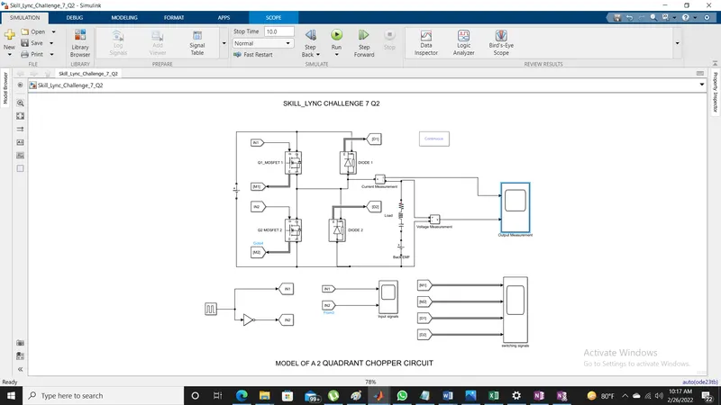
The model consist of a Battery source, two switching device ( Q1 and Q2) , Two diodes, A RLC load, small voltage source to model the Back EMF and Pulse Generator to active the switches.
Two MOSFET devices are used as the switching device naming MOSFET 1 and MOSFET 2. The Mosfets are activated using a Pulse generator whose signal is inverted using a NOT GATE, so that only one Switch is active at a time. if both swiches gets active simultaneously, a short circuit will be created which will damage the cicruit.
Two diodes are attached in the cicruits to control the flow of current and for protection.
when Q1 is active, the current flows through Q1, to the load, when Q1 is off the D2 will get active and conduct, the Output voltage will be equal to the Source Voltage and the direction of the current will get reversed. The current will flow throug D1 back to the Voltage Source.
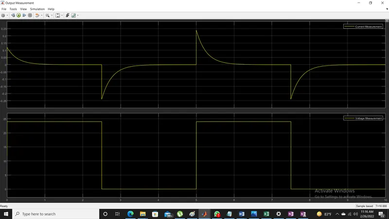
The simulink model has been attached along.
Answer 3:
Brushless DC motor is a DC motor whose commutation is done electronically. that is, it doesnt have brushes and uses an electronic circuit to switch the current.
The controller uses, switching devices to provide pulses of current to the motor windings to control the speed and torque of the motor.
BLDC are highly efficient at producing large amount of torque over a varied range of speed. BLDC use permanent magnets to rotate around a fixed armature.
BLDC's consist of two basic parts, the rotor and stator. The rotor consist of permanent magnets and the stator has the stator windings. High Power Transistors like mosfet and IGBTs are used to activate the electromagnet for the shaft to rotate. There is a controller which performs the power distribution using Power Electronics circuits.