Week -2
AIM:
- MODEL_1: Make a Simulink model of Doorbell using solenoid block
Condition: when the switch is closed the electromagnet receives electrical power from the battery and pulls the metal arm to hit the bell producing sound.
Simulate the situation where the switch is closed for 2 sec and then released
- MODEL_2: Use a thermistor to sense the temperature of a heater & turn on or turn off the fan
Condition: Temperature source:
- 20 °C from 0 to 10 seconds
- 27 °C from 10 to 30 seconds
- 23 °C from 30 to 50 seconds
Fan conditions: ON if the temperature above 25 °C, OFF otherwise
MODEL 1: DOORBELL USING SOLENOID
What is a Solenoid?
A solenoid is a long piece of wire which is wound in the shape of a coil. When the electric current passes through the coil it creates a relatively uniform magnetic field inside the coil.
The solenoid simply works on the principle of “electromagnetism”. When the current flow through the coil magnetic field is generated in it, if you place a metal core inside the coil, the magnetic lines of flux are concentrated on the core, increasing the coil's induction compared to the air core.
The magnetic strength of the solenoid can be increased by increasing the density of the turns or by increasing the current flow in the coil.
MODEL DIAGRAM :
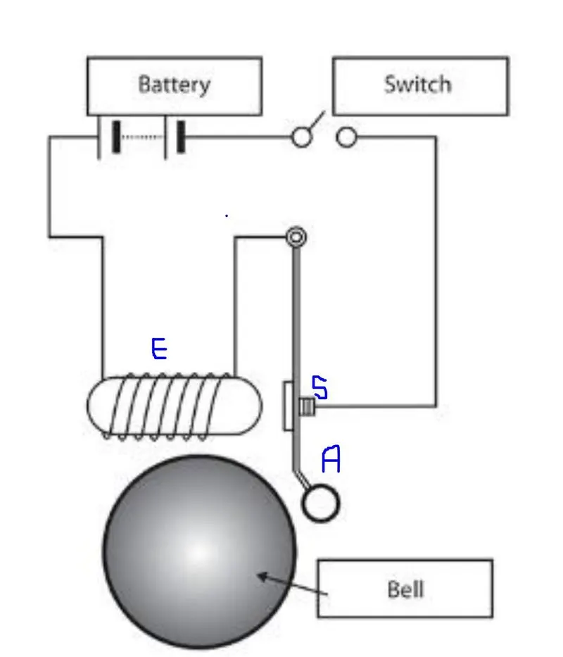
When the switch is closed the current flows through the circuit and gets to the Solenoid (the coil of wires wrapped around 'E'), an electromagnetic field is created. An armature made of iron/nickel (A), which has magnetic properties and turns into a temporary magnet, in turn getting attracted to the solenoid which is basically an electromagnet. This attraction results in the armature striking the bell 'B' and making the sound.
As soon as the switch is open, the current stops flowing and the armature returns to its original position via a spring(S).
Simulink Model of DOORBELL:
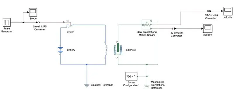
- The pulse generator is used to generate the single of 0 and 1 which signifies the open and close circuit.
- A scope is used to check the input signal.
- A Simulink-PS Converter is used to convert the Simulink signal into the physical signal.
- That signal is then connected to a switch that operates on the signal provided as input.
- Then an electrical circuit is created using a battery, solenoid, and switch in series connection.
- The output from the solenoid passes through the ideal translational motion sensor.
- Electrical reference and mechanical reference are connected to the circuit for reference.
- The results from the motion sensor are then converted to Simulink signal using a PS-Simulink converter
- The scope is used to show the position and velocity of the plunger for the input signal.
Pulse Generator :
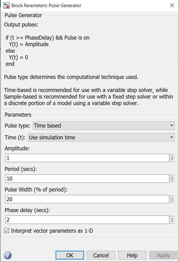
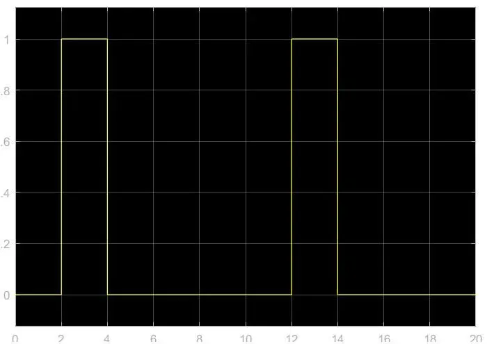
The pulse generator is used to generate the signal for a 20-sec simulation with a phase delay of 2 sec period of 10 sec and width of 20% of the period.
this input signal is going to be converted into a physical signal and the switch will operate according to this.
 |
 |
Solenoid:
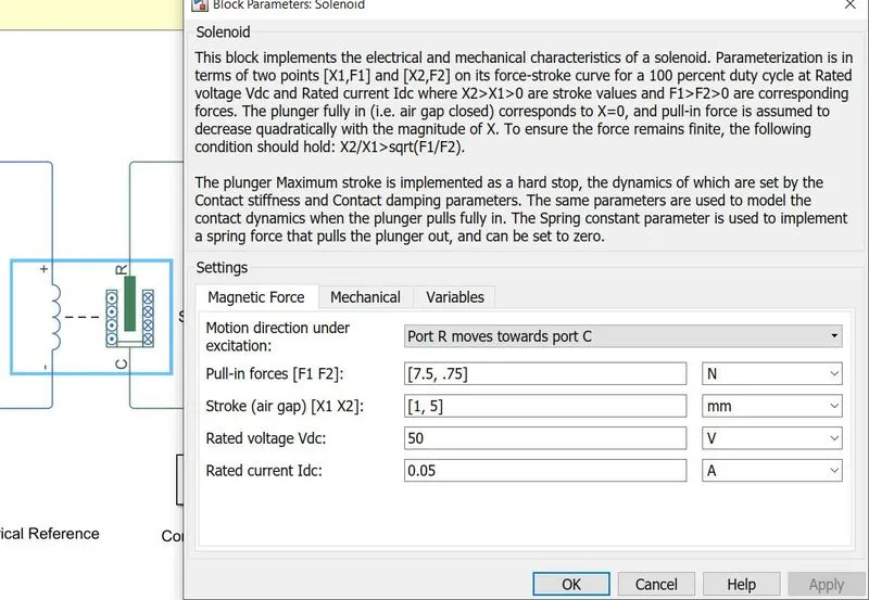
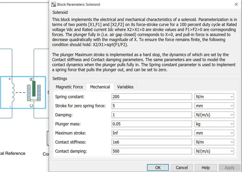
We can change the mechanical and magnetic force settings of the solenoid in our simulation for the current simulation the settings of the solenoid are
rated voltage is 50v, the spring constant is 200N/mm, damping coeff is 1N/(m/s) and the mass of the plunger is 0.05kg
| Magnetic force variables | Mechanical variables |
 |
 |
Battery:
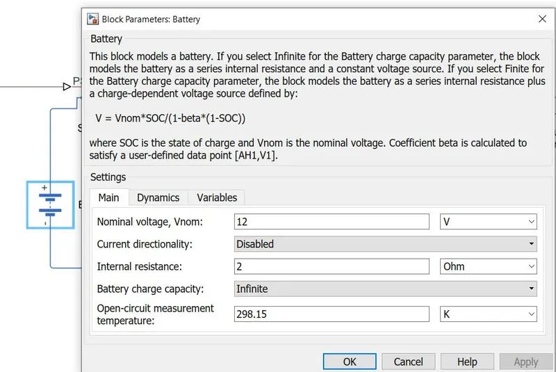
The battery is given the specification of 12v and internal resistance of 2ohms and the charge capacity of the battery is not going to degrade with time.
Results:
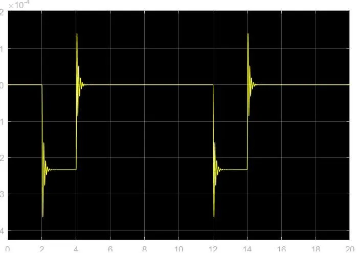
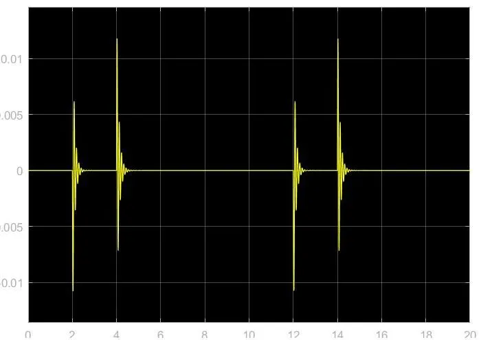
when the circuit is closed the plunger gets attracted to the magnetic field and the bells ring and as soon as the magnetic field is closed i.e circuit is open the plunger comes to stationary due to the spring action
movement of the plunger is explained with time
| Position of Plunger | Velocity of Plunger |
 |
 |
| Time | switch (on/off) | Action |
| 0-2 sec | off | the plunger is at rest |
| 2-4 sec | on |
movement can be observed at t=2sec as the magnetic field is on it attracts the plunger and rings. |
| 4-12 sec | off | t=4sec the magnetic effect if off the plunger is pullback by the spring back to the original position |
| 12-14 sec | on | movement can be observed again at t=12sec as the magnetic field is on it attracts the plunger and rings. |
| 14-20 sec | off | t=14sec the magnetic effect if off the plunger is pullback by the spring back to the original position |
Note:
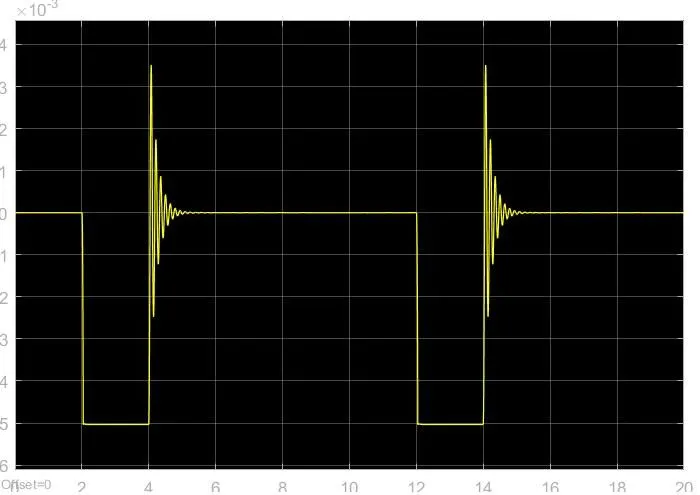
If the voltage of the battery is equal to the rated voltage of the solenoid that is in our case the voltage of battery= rated voltage of the solenoid=50v
then the opening movement of the plunger will be damped.
| Results with 12v Battery | Results with 50v Battery |
| Input signal | Input signal |
|
|
| Position of the plunger with time(12v) | Position of the plunger with time(50v) |
|
 |
| the velocity of the plunger with time(12v) | the velocity of the plunger with time(50v) |
|
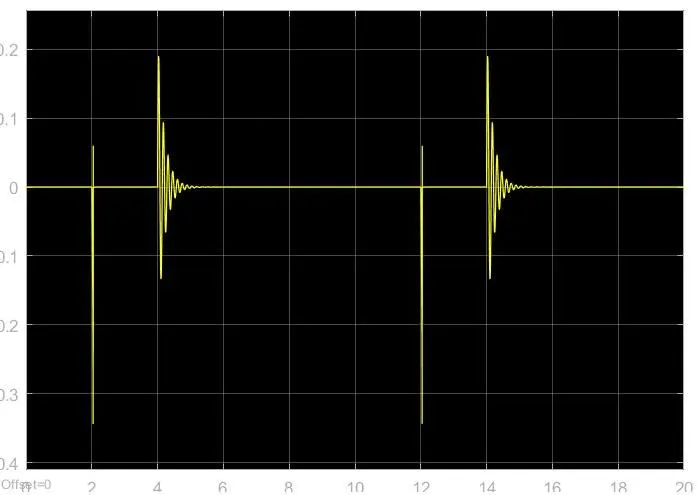 |
By changing the mass and damping of the solenoid system we can get a smooth graph as changing these variables will affect the motion of the plunger.
variables that affect the motion:
- spring stiffness
- damping coefficient
- plunger mass
MODEL 2. FAN MODEL TO OPERATE ON TEMPERATURE CONDITIONS USING THERMISTOR.
Thermistor: [ SOURCE :link_of_source ]
The term thermistor comes from “thermal” and “resistor”. A thermistor is a type of resistor whose resistance is reliant on temperature; it’s a resistance thermometer. They’re made from metallic oxide which is molded into a bead, disk, or cylindrical shape and then enclosed with epoxy or glass. Thermistors don’t work well with extreme temperatures, but they are perfectly suited for measuring the temperature at a certain point; they’re precise when they’re used within a limited temperature range i.e. within 50 °C of the target temperature; this range is dependent on the base resistance.
Working of a thermistor:
There are two types of thermistors –
- Negative Temperature Coefficient (NTC) thermistor. The NTC’s resistance decreases as the temperature increases, and vice versa.
- Positive Temperature Coefficient (PTC) thermistor, the resistance increases as the temperature increases, and vice versa; it’s normally used as a fuse.
The type of material used in the thermistor will dictate how much the resistance changes, which is changed with temperature. Thermistors are nonlinear i.e. the connection between resistance and temperature won’t form a straight line, it will form a curve on a graph; where the line sits and how much it changes depends on how the thermistor is made.
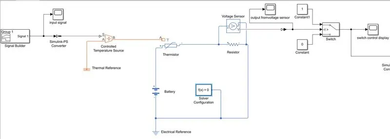
Simulink Model Of thermistor fan:
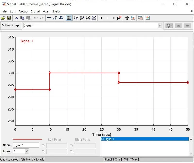
- Signal builder is used to generate signal as per the condition i.e 20*C(293 K)(0-10 sec), 27*C(300 K)(10-30 sec), 23*C (296 K)(30-50sec).
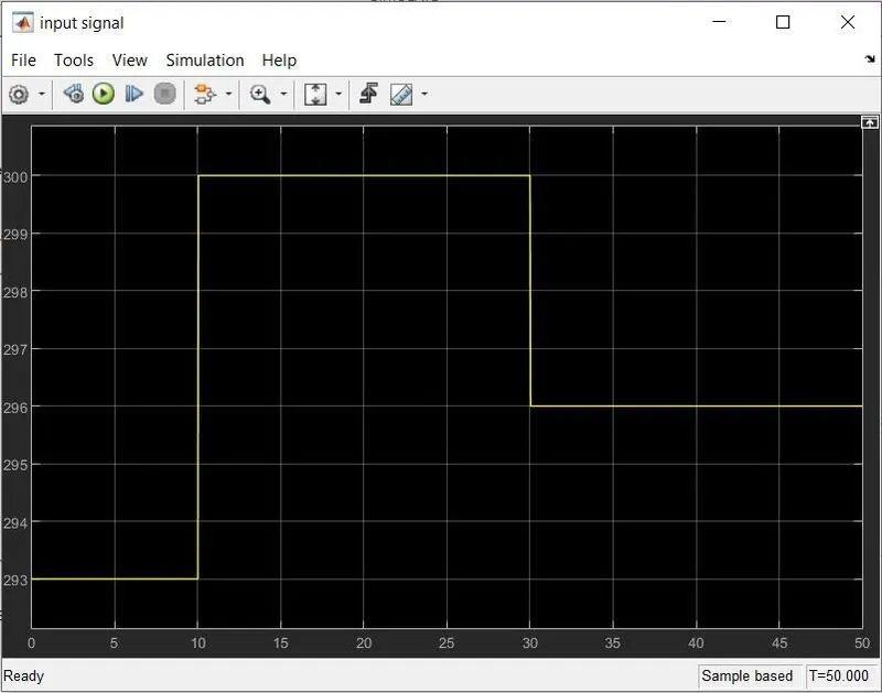
- a scope is used to read the input signal then it is changed to a physical signal using a Simulink-ps converter.
- then this signal is the input of the s port of the controlled temperature source
- the control temperature source a port is connected to the thermal reference then the output from this is connected to the thermistor.
- the thermistor is connected to the circuit consisting of batter and resistor
- as the temperature input from the control temp source change, the thermistor acts as a switch and allows current to flow as its resistance decreases with increasing temperature
- so when the condition is true that is temperature is above 25 C or 278 K the current flows through the circuit and the voltage drop across the resistor is measured through the voltage sensor
- the reading from the voltage sensor is converted to Simulinkand then the signal is seen through the scope and it is input for the switch that converts the input in form of an on and off signal i.e 0 and 1.
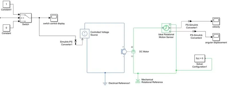
- the output after the switch is then passed through the controlled voltage source that is connected to the dc motor.
- the dc motor circuit consists of an ideal rotational motion sensor that gives the output of angular rotation and angular velocity.
- PS-Simulink converter is used to convert the physical signal from the ideal rotational motion sensor into a Simulink signal.
- electrical and mechanical reference is attached to the circuit for reference.
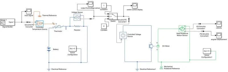
| Electrical circuit with the thermistor and the Input signal |
 |
| Fan circuit after the electrical circuit |
 |
Signal builder:
signal builder is used to create the signal as instructed in the condition
Condition: Temperature source:
- 20 °C from 0 to 10 seconds
- 27 °C from 10 to 30 seconds
- 23 °C from 30 to 50 seconds
| signal builder | scope reading of signal builder |
 |
 |
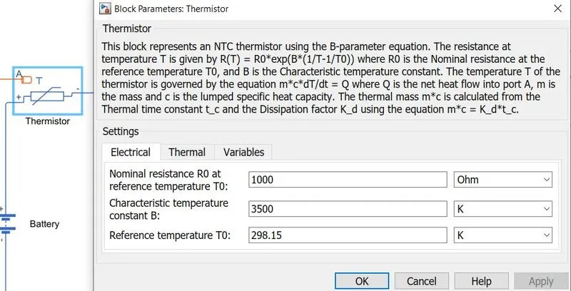
Thermistor:
the reference temperature of the thermistor is set to 25 C i.e 298 K
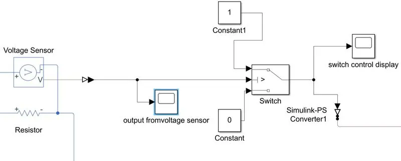
Modifying the signal output from the voltage sensor with a switch for fan circuit input.
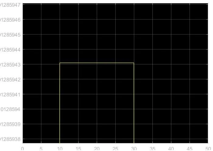
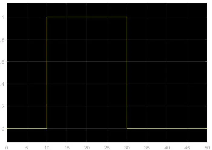
AS we get the reading from the voltage sensor when the temperature is above 25 C i.e. 298 K but there is no reading when the temperature is less than 25 C so to run the fan we need to convert this output signal through a conditional switch in the signal form of 0 and 1 to turn ON and turn OFF the fan.
So we give a threshold value to the switch and if the reading from the sensor is above that value it generates a signal of 1 and if it is below that value it generates a 0 signal.
| signal before switch | signal after switch |
 |
 |
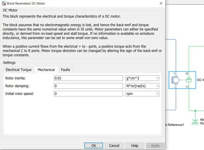
DC-Motor:
rotational inertia, rotor damping, and initial rotor speed can be defined in this model.
RESULTS:
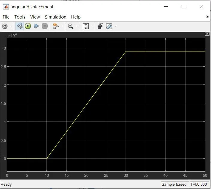
When the input temperature in our model goes above 25 C i.e 298K we can see the angular displacement and angular velocity of the fan increases from 0 and for the temperature below the 25 C the fan is at rest i.e it is switched OFF.
| INPUT SIGNAL VS ANGULAR DISPLACEMENT | INPUT SIGNAL VS ANGULAR SPEED |
|
|
 |
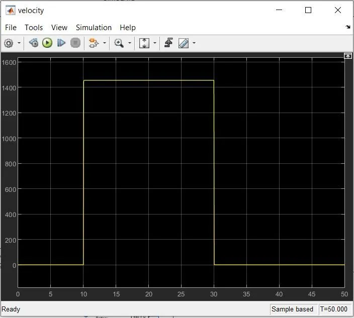 |
| WHEN THE TEMPERATURE IS ABOVE 25 C i.e 298 K WE CAN SEE THE ANGULAR DISPLACEMENT IN THE FAN | WHEN THE TEMPERATURE IS ABOVE 25 C i.e 298 K WE CAN SEE THE ANGULAR VELOCITY IN FAN |
ERROR:
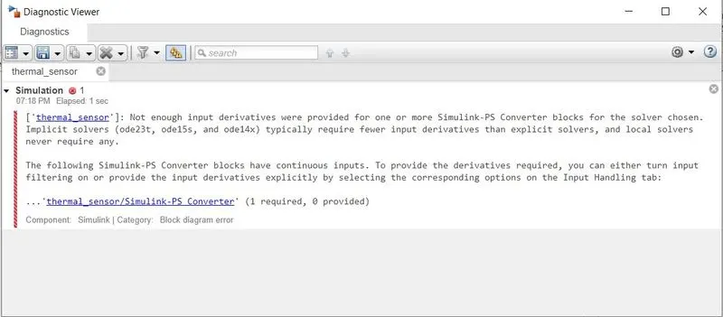
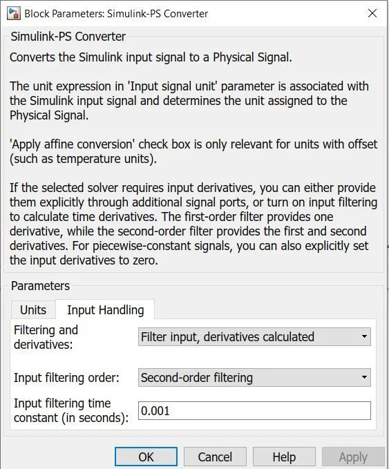
The model was throwing an error of not enough input derivate for our Simulink-PS converter block.
This error was solved by changing the input handling of the Simulink-ps converter and changing the filter option from signal input to derivatives calculated and input order filtring to second-order filtering.
Google Drive link for the above Simulink model
MODEL 1: Doorbell
MODEL 2: Thermistor fan