using_matlab_for_otto_cycle_of_engine_using_engine_kinematics_to_trace_volume
Thermal efficency of a engine and its otto cycle (including engine kinematics)
The Otto cycle is a set of processes used by spark ignition ic engines .
These engines
a) ingest a mixture of fuel and air
b) compress it
c) ignition, adding heat through converting chemical energy into thermal energy
d) expands and eject the combustion products and replace them with a new charge of fuel and air.
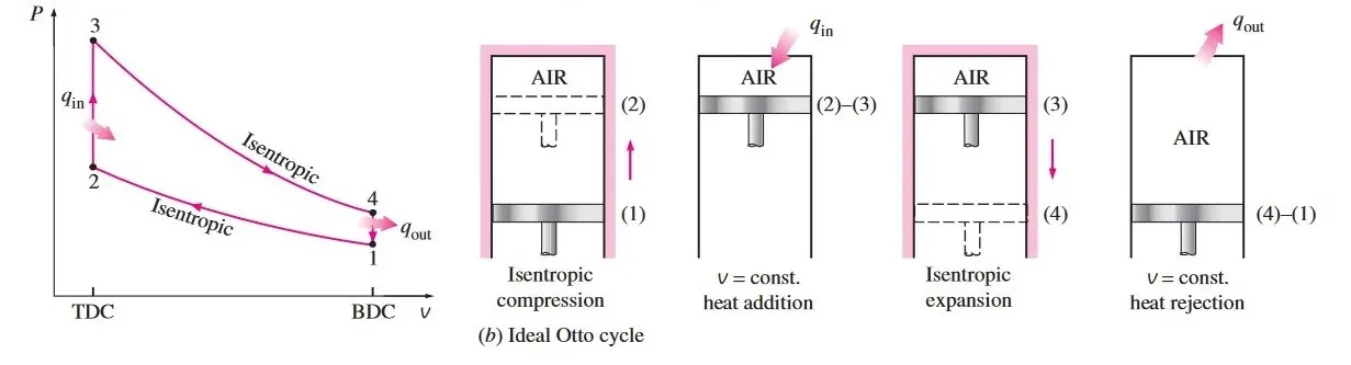
These processes can be explained in thermodynamics steps as
- (1 -2) Isentropic compression
Charge mixed with air is compresed inside the cylinder when piston moves from BDC to TDC.
- (2-3) constant volume hreat addition
when the piston reaches the TDC heat is added to the system with spark creating chemical energy to thermal energy this happens without any change in volume.
- (3-4) isentropic expansion
with force due to charge ignition the piston expands from TDC to BDC.
- (4-1) constant volume heat rejection
fresh air&fuel charge is taken in and heat is ejected through exaust.
*In an ideal otto cycle the volume change (dV) is constant with time that means it increases or decresses linearly with respect to time but practically in a engine cylinder the volume change is not linear it depends on the angular postion of the piston with crankshaft.
so we need to trace the volume change in the cycle.
Volume trace by engine kinamatics:
volume of the cylinder during compression and expansion can be traced out by using the formula:
V(theta)=(1+(0.5*(compression ratio-1))*((R +1-cosd(theta))-((R^2 - sind(theta).^2).^0.5))).*compressed_V
a=stroke/2
R=length of connecting rod/a
*ALL MATLAB PROGRAMS ARE EXPLAINED IN CODE ITSELF
Matlab code to compute the volume trace
STEPS
- input engine geometric values (bore dia,stroke,connecting rod length,compresssion ratio)
- calculate the value of constant a(stroke/2)& r (=connecting rod length/(stroke length/2)) to be used latter
- calculate the swept volume(pi/4)*dia^2 (bore dia)* length(stroke length)
- calculate the clearance volume (sweptvolume/(compression ratio-1))
- to calclate the volume change with theta(crank angle) store 720 values from 0 to 720*
- now to find the volume change with theta use formula
- V(theta)=(1+(0.5*(compression ratio-1))*((R +1-cosd(theta))-((R^2 - sind(theta).^2).^0.5))).*compressed_V
- to make it simpple divide the formula into 3 parts and add them
- part 1 d_1=0.5*(c_ratio-1)
part 2 d_2= r +1-cosd(theta)
part 3 d_3=(r^2 - sind(theta).^2).^0.5 - add these partsvto get the value of volume.
- using plot command plot volume with theta.
clear all
close all
clc

bore=0.1; % input bore dia
stroke=0.1;%input stroke length
c_rod=0.15;%input connecting rod length
c_ratio=12;%input compression ratio

%calculating the value of r
a=stroke/2;%as r=length of conecting rod by halh of stoke a=stroke/2
r=c_rod/a;

%calculating the swept volume and clearance volume
v_s=pi/4*bore^2*stroke;%calculating swept volume
v_c=v_s/(c_ratio-1);%caculating the clearance volume

theta=linspace(0,720,720);% creating a array to  store the angular values of crank rotaion

%now as the voluume trace in engine is calculated by:
%V(theta)=(1+(0.5*(compression ratio-1))*((R +1-cosd(theta))-((R^2 - sind(theta).^2).^0.5))).*compressed_V
%we will devide the formala in 3 parts as it will be complicated to understand

d_1=0.5*(c_ratio-1);% part 1
d_2= r +1-cosd(theta);%part 2
d_3=(r^2 - sind(theta).^2).^0.5;%part 3

% adding these there parts to get the value of volume at a perticular angle
v=(1+d_1*(d_2-d_3)).*v_c;
%ploting these volume trace
plot(theta,v,'linewidth',3) 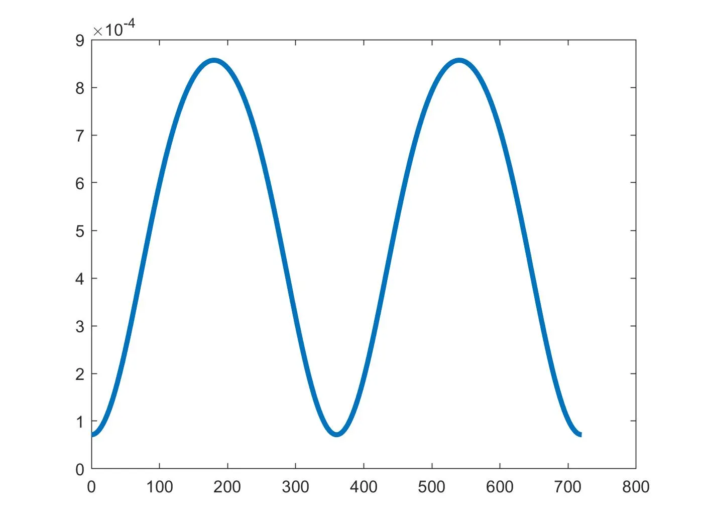
change in volume with theta
we will convert this program into a function to be called in otto cycle program to to trace the volume using engine kinamatics
STEP
function [y1,...,yN] = myfun(x1,...,xM)
WHERE y1,y2,...yn is the returned value from thr function
and "myfun" is your function name
(x1,x2,.....) are the input values of the function when called
- using the above define the volume v as output from th function
- define the funtion name (*same as function file name)
- take the engine geometric values(bore dia , stroke ,c_rod,c_ratio,start crank angle and end crank angle
- remove these input from the previous function and remove the plot command
engine_kinematics_fn
%function requires bore dia stroke length connecting rod length
%compression ratio start crank ange and end crank angle
function [V] = engine_kinematics_fn(bore,stroke,c_rod,c_ratio,start_crnk_angl,end_crnk_angl)
%calculating the value of r
a=stroke/2;%calculating the value of r
r=c_rod/a;

%calculating the swept volume and clearance volume
v_s=pi/4*bore^2*stroke;%calculating swept volume
v_c=v_s/(c_ratio-1);%caculating the clearance volum

% creating a array to  store the angular values of crank rotaion
theta=linspace(start_crnk_angl,end_crnk_angl,100);

%now as the voluume trace in engine is calculated by:
%V(theta)=(1+(0.5*(compression ratio-1))*((R +1-cosd(theta))-((R^2 - sind(theta).^2).^0.5))).*compressed_V
%we will devide the formala in 3 parts as it will be complicated to understand

d_1=0.5*(c_ratio-1);% part 1
d_2= r +1-cosd(theta);%part 2
d_3=(r^2 - sind(theta).^2).^0.5;%part 3

% adding these there parts to get the value of volume at a perticular angle
V=(1+d_1*(d_2-d_3)).*v_c;
end
MAIN FUNCTION
EXPLAINATION:
1. swept volume is not linear it depends on the the crank rotation.
its trace can be find by using the formula.

used in engine kinematic function
2. For isentropic process:
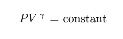
and ideal gas equation
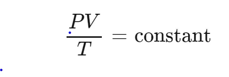
used to find the state variable at 2-3-4
3. to find thethermal efficency of the engine
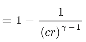
where cr is compression ratio and gamma is cp/cv
ASSUMPTIONS:
VALUES AT POINT 1 AND TEMPRATURE AT 3 ARE KNOWN
P1 = 102432 pa (1 atm)
t1= 500k
t3=2300k
Engine geometric values are also known
- Bore diammeter=0.1
- stroke length=0.1
- connecting rod length=0.15
- compression ratio=12
- Gamma=1.4 (for air)
Steps:
- input the assumption value of state variable p1 t1 and t3
- input the assumption value engine geometric values
- calculate the value of constant a(stroke/2)& r (=connecting rod length/(stroke length/2)) to be used latter
- calculate the swept volume(pi/4)*dia^2 (bore dia)* length(stroke length)
- calculate the clearance volume (sweptvolume/(compression ratio-1))
- calculate the vriable v1 nd v2 as sweptvolume + clearance volume and clearance volume respectively
- for 1-2 using p2v2^gamma = p1v1 ^ gamma find p2=p1*c_ratio^gamma
- and using p1v1/t1=p2v2/t2 find t2 (t2=p2*v2*t1/(p1*v1))
- call the finction to get the volume trace for compresion stroke v_comp
- using const_c=p1*v1^gamma
find p_comp=const_c./v_comp.^gamma - using p3v3/t3=p2v2/t2 find p3=p2*t3/t2
- call the finction to get the volume trace for expansion stroke v_exp
- using const_c=p3*v33^gamma
find p_exp=const_c./v_exp.^gamma - compute v4 and p4 using |v4=v1 | p4=p3*(v3/v4)^gamma;
- now as for ignition and exhaust stroke volume is constant so p2-p3 and p4-p1 is a straigth line so devide the values of volume and pressure into 20 arrays using line space comand
- no using figure and hold on command to hold the plots
- using plot command plot (v_comp,p_comp),(v_ig,p_ig),(v_exp,p_exp)and (v_ex,P_ex)
- also plot the points 1-2-3-4.
- to calculate the thermal efficency use formula thermal_effi=1-((v3/v4)^(gamma-1))
clear all
close all
clc

%starting assumptions

%input variable
gamma=1.4%constant for the process

%state variable
t3=2300 %tempprature of charge at ingition
p1=102432%intake pressure of charge in cylinder
t1=500 %intake temprature of charge

%engine geometric parameters
bore=0.1;%bore dia of cylinder
stroke=0.1;%length of stroke
c_rod=0.15;%length of connecting rod
c_ratio=12;%compression ratio

% calculating the swept volume and the clearance volume
v_swept=(pi/4)*bore^2*stroke;% swept volume
v_clearance=v_swept/(c_ratio-1);%clearance volume

v1=v_swept+v_clearance;%total volume
v2=v_clearance;

%state variable at state point 2

%p2v2^gamma = p1v1 ^ gamma
% p2=p1*(v1/v2)^gamma = p1*cr^gamma
p2=p1*c_ratio^gamma;

%p1v1/t1=p2v2/t2 |t2=p2*v2*t1/(p1*v1)
t2=p2*v2*t1/(p1*v1);

const_c=p1*v1^gamma;% to claculate the pressure
v_comp=engine_kinematics_fn(bore,stroke,c_rod,c_ratio,180,360);%function call to caljucate the volume
p_comp=const_c./v_comp.^gamma;%pressure calculation at 2-3

%stae variable at state point 3

v3=v2;% since heat is only added in the process without volume change

%p3v3/t3=p2v2/t2 | p3=p2*t3/t2
p3=p2*t3/t2;

const_c=p3*v3^gamma;%to calculate pressure
v_exp=engine_kinematics_fn(bore,stroke,c_rod,c_ratio,0,180);% function call to calculate the volume change
p_exp=const_c./v_exp.^gamma;% prsuure  calulation through point 3-4


%state variable at state point 4
v4=v1;

%p3v3^gamma=p4v4^gamma | p4=p3(v3/v4)^gamma
p4=p3*(v3/v4)^gamma;

%to plot the process 2-3
%pressure clculation for constant volume heat addition
v_ig=linspace(v2,v2,20)% volume remains same for the process 20 values saved to  v_ig
p_ig=linspace(p2,p3,20)%  pressure at  point 2 and 3 is divide into 20 values to plot the cycle

%to plot the process 2-3
%pressure clculation for constant volume heat rejection
v_ex=linspace(v4,v1,20)% volume remains same for the process 20 values saved to  v_ex
p_ex=linspace(p4,p1,20)%  pressure at  point 4 and 1 is divide into 20 values to plot the cycle


% ploting the otto cycle
figure(1)
hold on% to hold the graph
plot(v_comp,p_comp,'color','r','linewidth',1.5)%proocess 1-2
plot(v_ig,p_ig,'color','y','linewidth',1.5)%process 2-3
plot(v_exp,p_exp,'color','b','linewidth',1.5)%process 3-4
plot(v_ex,p_ex,'color','y','linewidth',1.5)%process 4-1
%for pointing the state value
plot(v1,p1,'*','color','g')%at state 1
plot(v2,p2,'*','color','g')%at state 2
plot(v3,p3,'*','color','g')%at state 3
plot(v4,p4,'*','color','g')%at state 4
xlabel("volume")
ylabel("pressure")
grid on

%to get the value of thermal efficency of the cycle
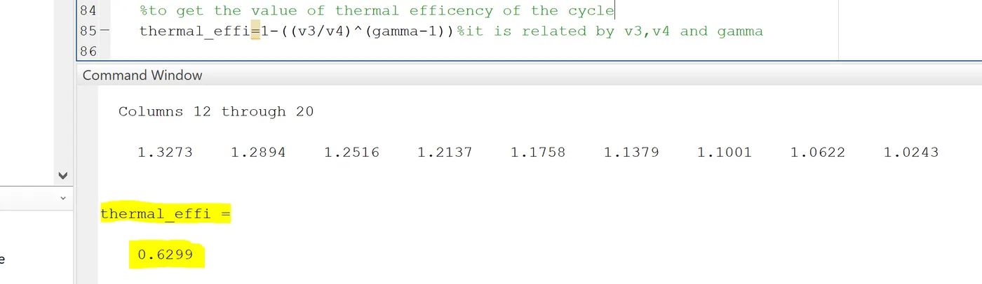
thermal_effi=1-((v3/v4)^(gamma-1))%it is related by v3,v4 and gamma
Results
as the volume change with theta the trace is not linear so for the process 1-2 and 3-4 compresion and expansion
change with with theta and for the process 2-3 and 4-1 there is constant volume heat adition and constant volume heat rejection there is a suddden increase in pressure due to ignition and exhaust process.
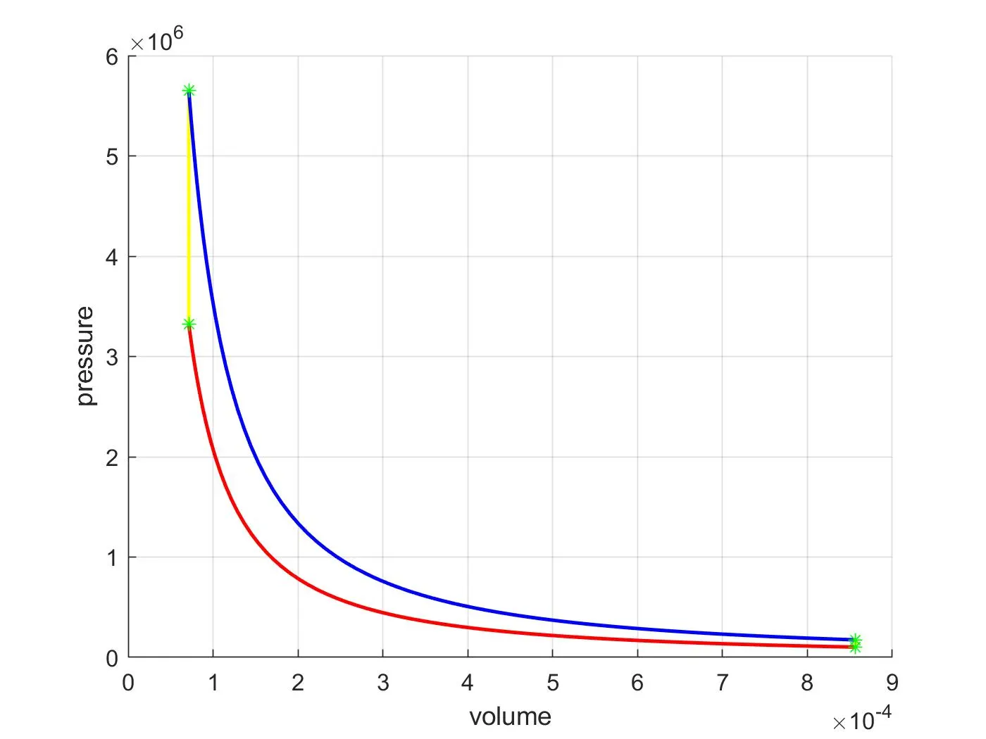
the thermal efficency of the cycle can be determind as
thermal_effi=1-((v3/v4)^(gamma-1))
where v3 is the clearance volume and v4 is (swept +clearance volume )
and gamma is cp/cv
thermal efficiency is 0.6299 or 62.99%