Week 14 challenge
OBJECTIVE:
The main objective of this project is to understand the fundamentals of GD&T and apply them to the design of a butterfly valve using Siemens NX.
INTRODUCTION:
GD&T stands for Geometric Dimensioning and Tolerancing. It is a standardized way of communicating information about a product and it is applied to engineering drawings with the set of geometric symbols and annotations following the standards. GD&T is an important skill to understand In the manufacturing industry. It is like a language that helps to understand a product between design engineers, manufacturers, and quality inspectors. Any product is first designed by a design engineer, manufactured by a manufacturer, and inspected by an inspector of the metrology department. For this process to work, all the professionals in this process must communicate effectively and efficiently in every step of the process to reduce the failure of parts and increase the accuracy. A CAD is perfect but there is no such manufacturing method that fracturing I can replicate the exact CAD file into the physical world with perfection. This may lead to failure or disqualification of many parts during the inspection. To meet the design intent of the design engineer and make the process of manufacturing and inspection faster, proper communication is required. A CAD is perfect but the reality is not, which is why need to define how far and in what ways our physical product can vary from the CAD model. GD&T is, therefore, applied to every engineering drawing before it goes to a manufacturer. Trying to get the perfect result or very tight tolerance increases the cost, so it is discussed with the customers how much tolerance to provide for the parts.
A butterfly valve is a type of valve which helps to regulate the flow of fluid in a pipe using a disc. It consists of parts like the housing, stem or shaft, disc plate, retainer, lever, and nuts. Screws are required to fix the parts in their respective position providing the required DOF for the moving parts.
In this project, a typical butterfly valve is designed and is assembled in NX CAD and GD&T is applied to all the individual parts including the assembly of the butterfly valve. Proper size and geometric tolerances
can be applied to define the part drawing completely. GD&T has various standards like ASME Y14.5, ISO, etc. In this project, GD&T is applied following the standard of ASME Y14.5 2009.
METHODOLOGY:
For this project, the entire design, assembly, and drawing creation is done using the Parametric CAD software, Siemens NX. First, each part is designed in NX, and a drawing for each is created after which GD&T is applied to the drawing. The approach for the completion of this project is shown in the methodology flowchart below.
Part Creation:
As in most of the CAD packages, NX also requires base sketches for the part to be designed. The sketch can be first drawn. and the feature can be applied later. Also, the sketch can be created after using the feature command and the sketch can be created within the command. All the parts for this butterfly valve are created in the modeling. t environment of NX
Assembly Creation:
Assembly creation in NX is a very simple
The method as it allows to preselect the joints and to move the components in the assembly process as per the design intent. Most of the mates used for this assembly are the Aligning of axis and touch mates or joints. Also, align mates. are applied somewhere as per the requirement. Since NX CAD is a parametric CAD software, it allows to change any feature or joints later at any point in time or to update the design with the same changes in the model.
Application of GD&T:
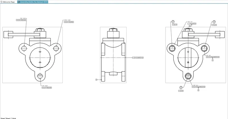
After each part is designed under the application, modeling in NX, the drafting application is chosen to create a drawing for individual parts. After the drawing is created using the required drawing views, proper GD&T is applied as per the requirements of various parts Application of GD&T in NX is a very simple and effective process because it allows applying any kind of Geometric Tolerancing symbols and tolerances with a few clicks. The feature control frame and datums can be applied easily as per the requirement following the standard.
DESCRIPTION:
All the individual parts designed in NX are described with the process of design drawing creation, and the application of GD&T.
ASSEMBLY OF BUTTERFLY VALVE:-
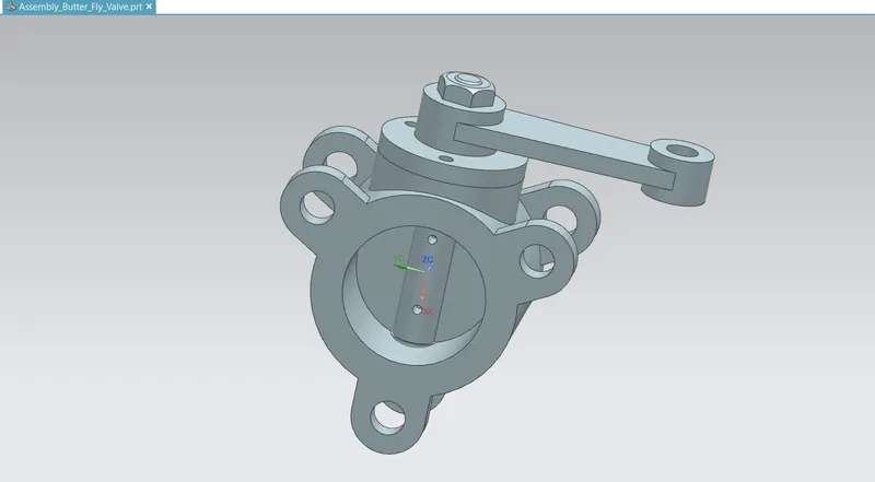
After completing the modeling of various components of a butterfly valve, all parts were assembled together using the Seimens nx assembly workbench.
CONCLUSION
The butterfly valve was successfully designed and GD&T was applied to all parts and the assembly of the butterfly valve.