Week 14 challenge
Parts of assembly are as follows:-
1.BODY OF BUTTERFLY VALVE
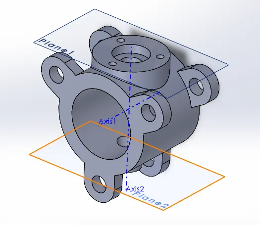
2.HANDLE OF BUTTERFLY VALVE.
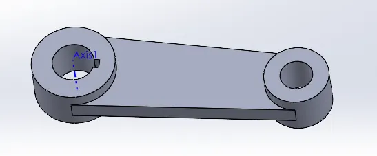
3.NUT OF BUTTERFLY VALVE.
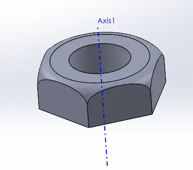
4.PLATE FOR BUTTERFLY VALVE.
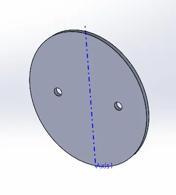
5.RETAINER FOR BUTTERFLY VALVE.
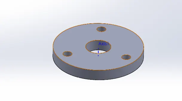
6.SHAFT OR STEM OF BUTTERFLY VALVE.
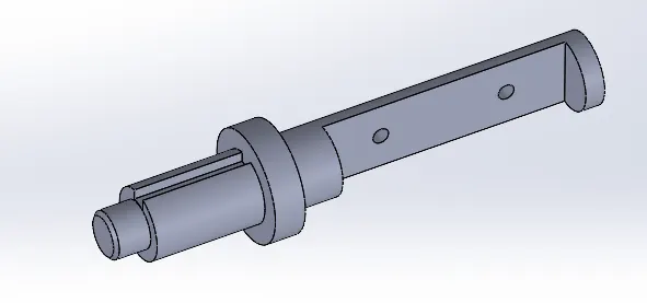
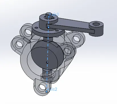
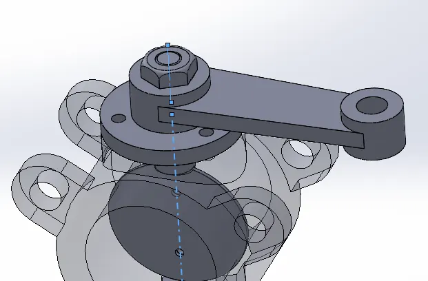
With the use of mate command entire assembly is done few images of that is attached below.
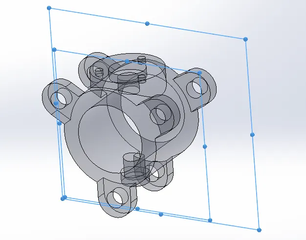
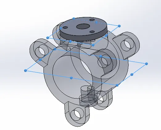
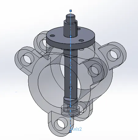
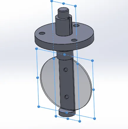
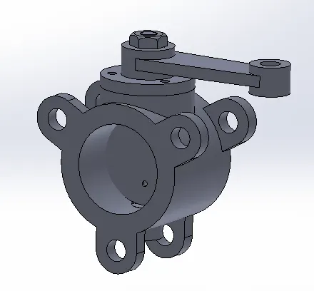
Final assembly image is shown below:-
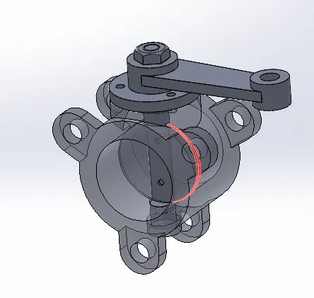
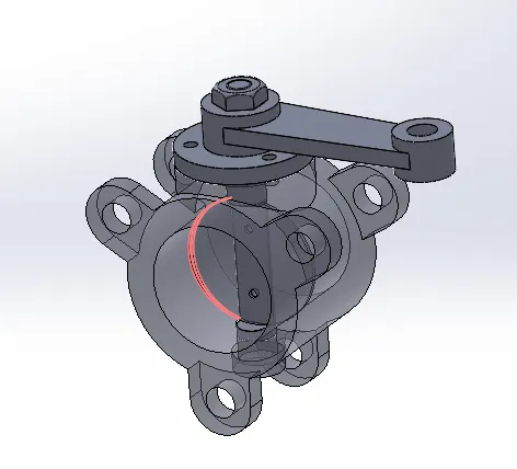
An interference is detected between BODY and PLATE the images of which are attached below.
Now ,when we are applying GD&T on any part then we first need to think that the part is going to produce in mass quantity to validate the produced outcome we need to have some quick good inspection setup like an inspection fixture,or use of CMM as per parts simplicity to complexity.
In any manufactured part the variations occur in size,form,orientation and location.the GD&T consist 5 tol.type &14 Geometrical characteristics as below:-
Form(straightness, Flatness, circularity, cylindricity)
Orientation (parallelism, perpendicularity, angularity)
profile(profile of a line,profile of a surface)
Runout (circular runout,total runout)
Location (position, concentricity,symmetry)
Before, applying GD&T concept is what is mfg process elected and by which process it is finished.
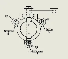
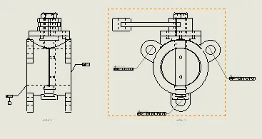
Primary datum is created by considering datum targets with diametrical region of 60mm and 3 Datum targets are applied to all the 3 region near holes.Flatness is to be controlled within range of 0.2mm.the exact opposite parallel face is controlled with profile of surface within tolerance range of 0.05mm.
Secondary datum is applied to one of 3 holes located at right side of part controlling it's perpendicularity with diametrical tolerance Range of 0.01 at MMC w.r.t A.
Similar manner third datum is another hole with same symmetric size tolerance but controlled in it's position by diametrical range of 0.01mm at MMC w.r.t datum A and datum B at maximum material boundary.
Then another datum D is added and applied to bottom located 3rd hole with same size tolerance and controlled in it's position by diametrical tolerance range of 0.01mm at MMC w.r.t datum A, B at maximum material boundary,C at maximum material boundary.
In the third view as in attached drawing file these side the hole which is exactly opposite to datum B is controlled in it's position with diametrical tolerance zone of 0.05 at MMC w.r.t datum A, B at maximum material boundary.
The hole opposite to datum C is controlled in it's position by diametrical tolerance zone of 0.05mm at MMC w.r.t datum A, B at maximum material boundary, C at maximum material boundary.
The hole opposite to datum D is controlled within it's position by diametrical tolerance zone of 0.05mm at MMC w.r.t datum B at maximum material boundary, datum C at maximum material boundary, datum D at maximum material boundary.
The images of application of GD&T on assembly model drawing are attached below:-