Week 9 - Challenge 1 - Base Bracket Design
BASE BRACKET DESIGN
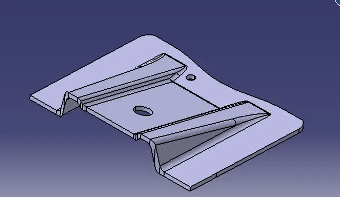
INPUT I GOT?
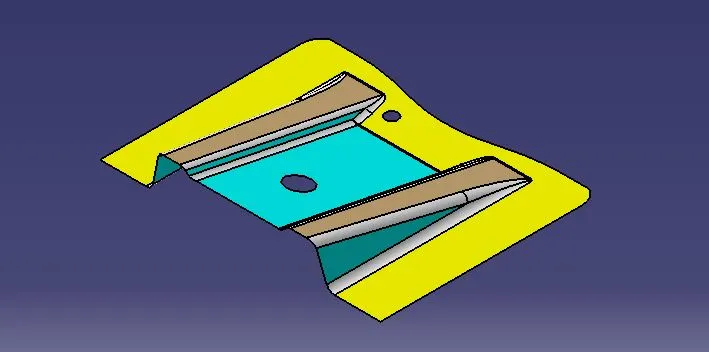
an CLASS A SURFACE.
WHAT IS TOOLING AXIS ?
Basically to manufacture or for production of any plastic part, we needed an tool (which consist core & cavity) generally plastic injection molds are preferred. The one of main base parameter for creation of mold is tooling axis with proper orientation.
HOW IT IS CREATED?
To create tooling axis on any component,easy way to start is look for flat face or check for any hole.
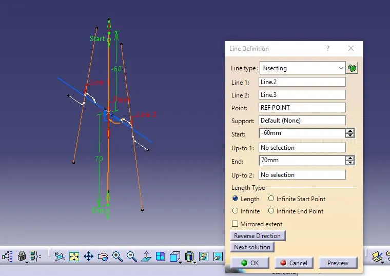
- create a dummy axis by normal procedure of creating axis from line command.
- intersect the plane & CLASS A surface,select the appropriate plane one among three(xy,yz,zx) in such a way that the it could easily ejected with no or less amount of side core movement.
- extend the angled lines.
- create bisecting line with the two angled line as reference along with reference point(through which dummy axis & plane was created).
WHAT IS DRAFT?
draft is nothing but a tapered angle is provided on vertical faces which are parallel to the direction of ejection,in order to eject the component securely without frictioning the plastic product walls with tool walls. general draft angles provided are in the range of 0.5 deg to 3 deg in mold tooling industry.there might be exceptional cases where we go beyond this range but very rarely those instances came up.
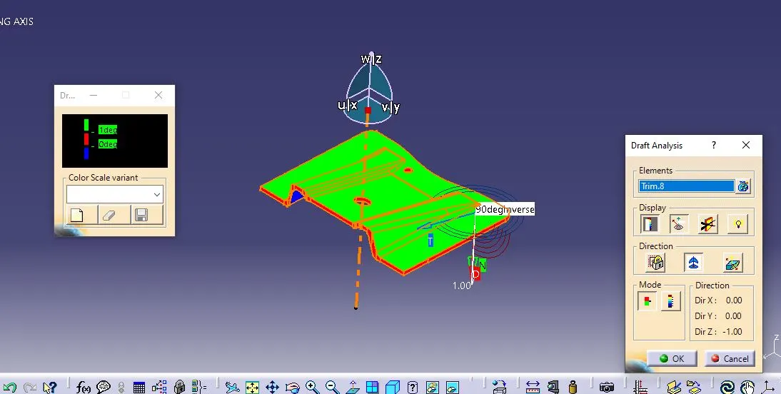
For this challenge I took 1 deg as a draft angle,as its a better practice to keep it minimum.
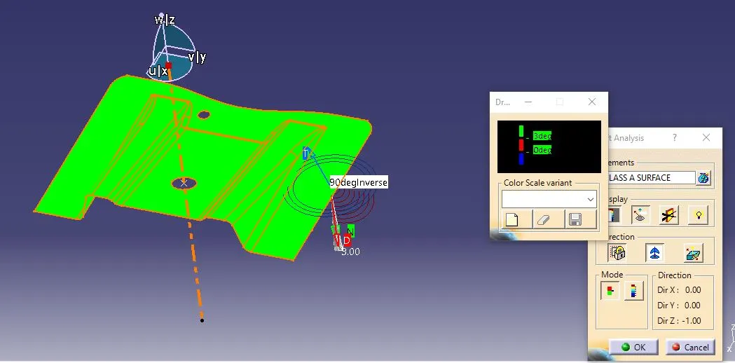
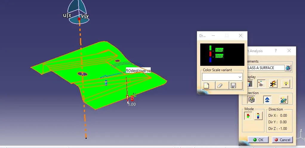
The above two pictures shows the result obtained in the draft analysis on CLASS A SURFACE.
the green coloured part shows that considering the inputed draft angles for surface with reference to tooling axis it is safe.
B SURFACE CREATION
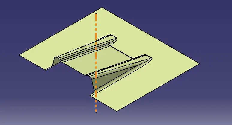
C SURFACE CREATION
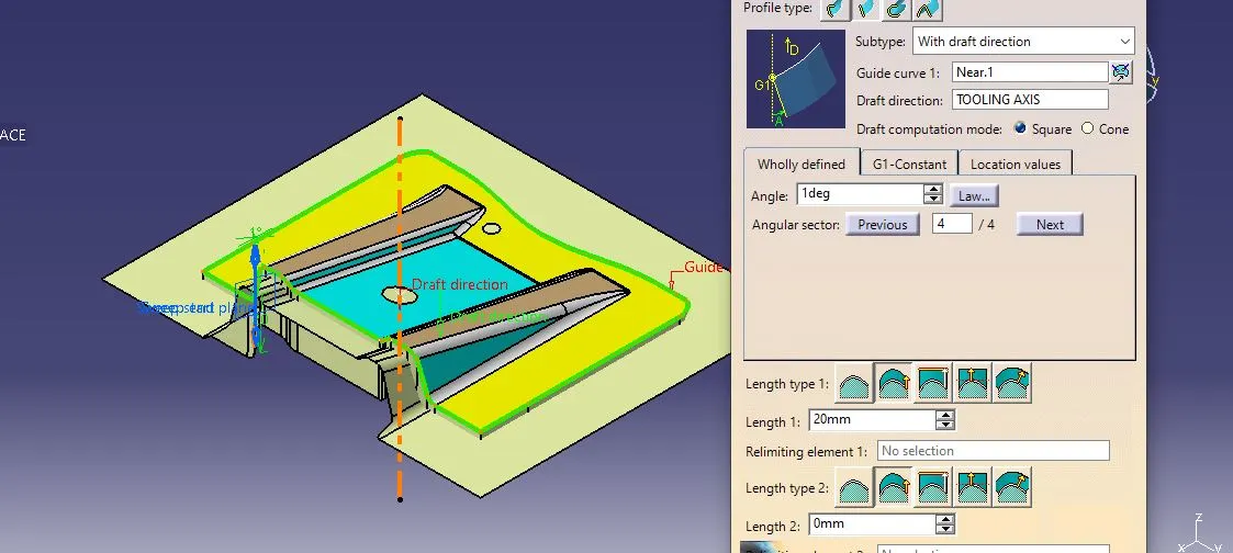
FINAL TRIM
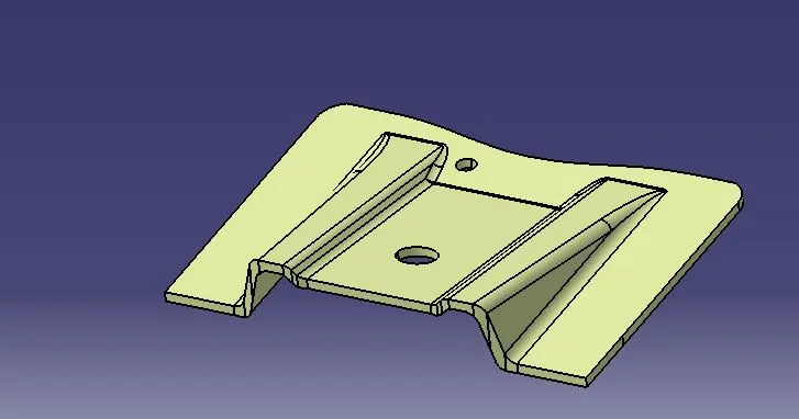
SOLID BODY CREATION WITH CLOSE SURFACE
DRAFT ANALYSIS ON SOLID PART
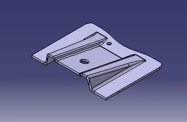
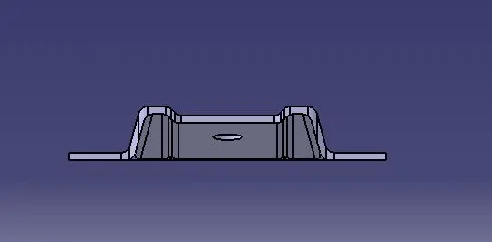
VIEWS
ISO
FRONT
TOP
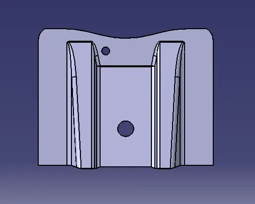
SIDE VIEW