Week 9 - Challenge 2 - Switch Bezel Design
SWITCH BEZEL DESIGN
TOOLING AXIS CREATION
1st axis reference
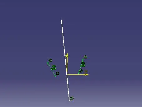
HERE While creating reference i took up two angled lines, whose are taken by intersection command and draw the bisecting line.
2nd Axis reference
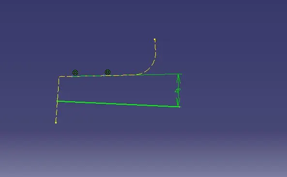
here as only single angled surface was there so i have drawn the other angled line at an angle of 4 deg.
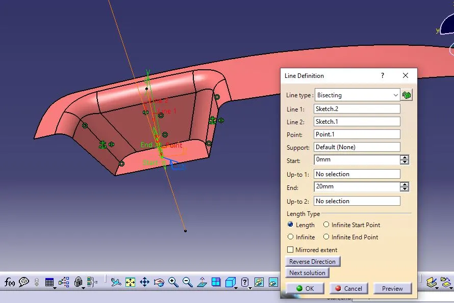
Tooling axis creation with the help of bisecting line on class A surface.
it is created using bisecting line with ref. point
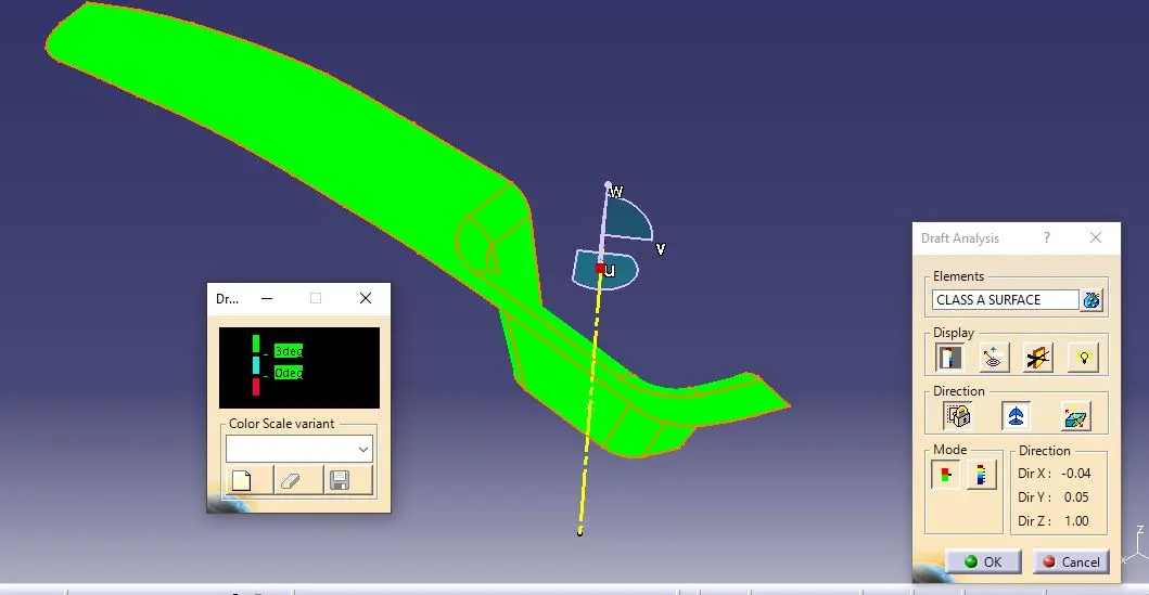
Draft analysis on CLASS A SURFACE.
class A Surface is checked for draft angle of 3 deg
with color code as follows:
GREEN colour:- positive draft.
RED colour:- negative draft.
CYAN colour:- zero draft.
CLASS B SURFACE
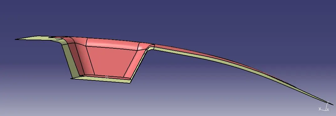
CLASS C SURFACE
class c surface is created with 2.6 deg angle.
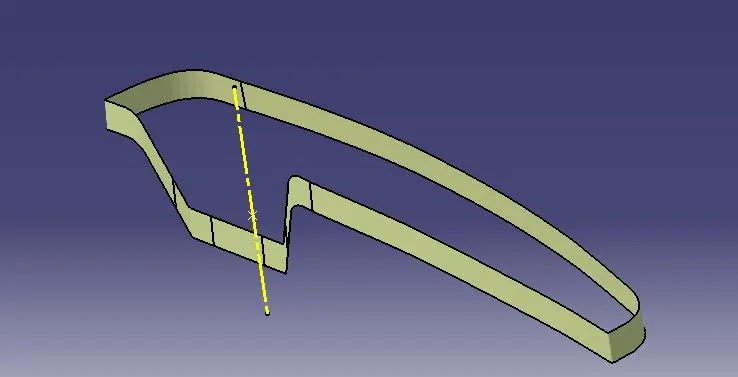
FINAL TRIM
during creation of final trim initially the gaps are seen,so to avoid it i increased the meshing gap of JOIN created between class A and class C surface from 0.001 to 0.003.
despite of that it was still showing gap so i extrapolated class A surface by 0.05 in all directions
so i finally got final trim with zero gaps.
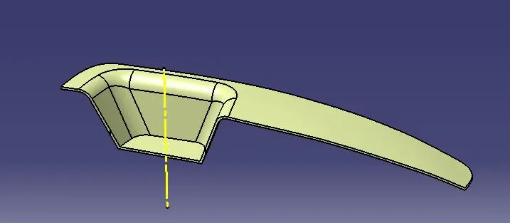
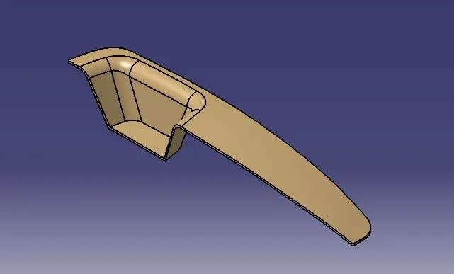
FINAL OUTCOME WITH CLOSED SURFACE
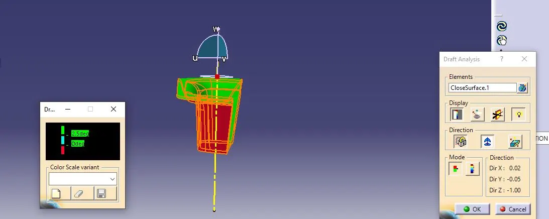
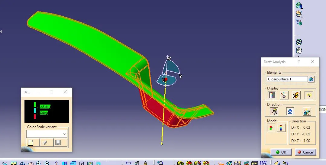
ISOMETRIC VIEW WITH DRAFT ANALYSIS
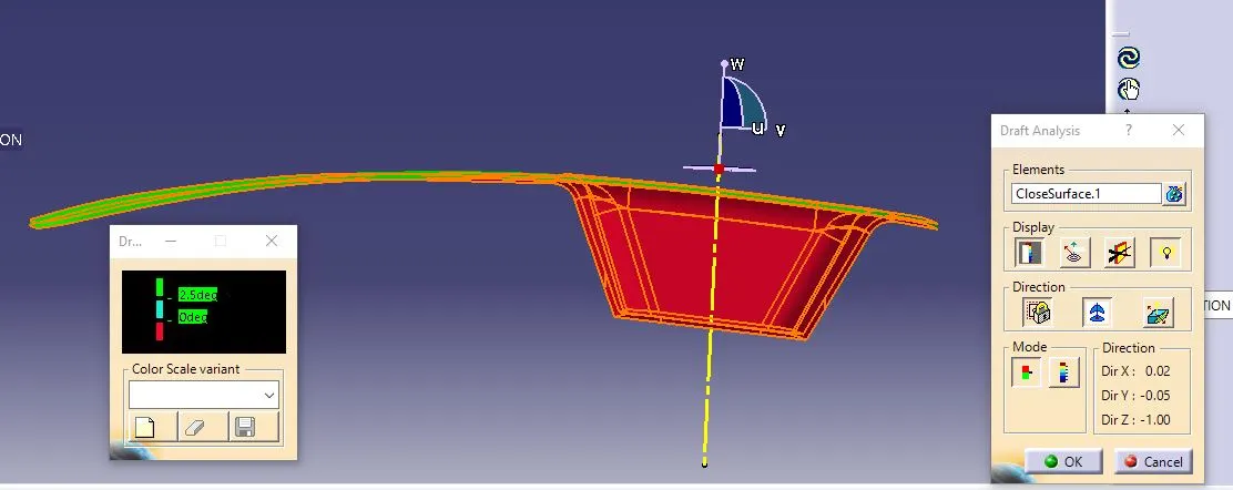
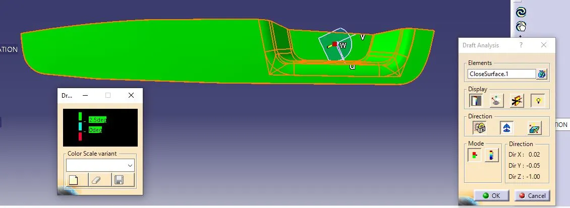
on final outcome draft analysis is done for 2.5 deg
as when i tried out with 2.6 deg the vertical faces shown up with cyan color.
FRONT VIEW WITH DRAFT ANALYSIS.
TOP VIEW WITH DRAFT ANALYSIS.
SIDE VIEW WITH DRAFT ANALYSIS.